PART8Basic Electrical Circuit
Experiment 6 :Relay Characteristic
Theory
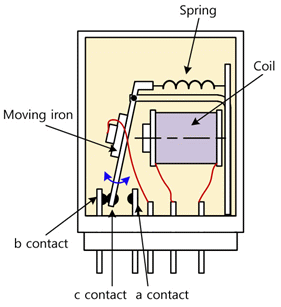
Relay is a component that executes operation of electrical and electronic equipments and signal delivery function. AS fig.8-23, the principle that the iron core becomes an electromagnet when the current flows to the core wound with the coil is applied, and this is a general purpose component applied to almost all electronic and communication equipments
As in fig.8-24, the electromagnetic contactor is composed of a-a contact and b-b contact, and in case of relay, it is composed as three-way switch type as a-com-b.
As the symbols in fig.8-24, the operation is executed in the same way as the expression. However, the relay has a com terminal additionally. One difference is that the com terminal becomes a contact when it is with the a contact and b contact when it is with the b contact.
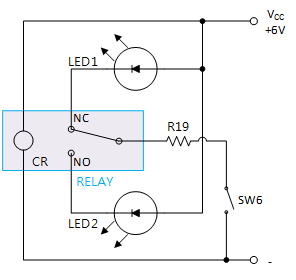
Fig.8-25 is a relay experiment circuit. If the power is not supplied to the relay coil(CR), the current flows through LED1 - NC(Normal Close) contact - traveling contact - R19. When VCC is supplied to the relay coil. The traveling contact moves to NO(Normal Open) contact and the current flows through LED2.
Experiment Process
1. Using Block f of M08, make a connection as in fig.8-25.
- Turn on the SW6, and connect between the relay coil and the earthing.
2. Connect the power of power supply as DC 6V.
- Check out which LED is turned on.
- Check out if the current flows through the coil of relay.
3. Remove the connection between the relay coil and the earthing.
- Check out which LED is turned on.
- Check out if the current flows through the coil of relay.
4. Reconnect between the relay coil and the earthing, and compare the state of LED. Is the result same as above?
tab1Experiment 8-6.1 Relay Circuit Experiment (In Block f of M08, compose a circuit as in fig.8-25.)
1.Connection(M08의 block f)
1.Circuit Connection
In Block f of M08 board, connect between the lower terminal of relay coil and the right earthing terminal with yellow line.
2.Power Connection
Connect between V1 termiinal of Variable Power on the left of M08 board and V+ terminal of Block f with red line, and between COM terminal and the earthing terminal with black line.
2.Wiring Diagram
3.Measurement
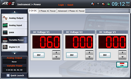
- 1Choose variable power at left menu of Touch LCD panel and set up at 3 CH DC for DC Voltage V1 to become 6V.
Click , and supply the output of DC 6V to the circuit.
Turn on the SW6 and record the measured result in the relevant column of table 8-11.

Check out which LED is turned on.
Check out if the current flows through the coil of relay.
- 2Remove the connection between the relay coil and the earthing and record the measured result in the relevant column of table 8-11.
Check out which LED is turned on.
Check out if the current flows through the coil of relay.
- 3Reconnect between the relay coil and the earthing, and compare the state of LED. Is the result same as above?
- 4After the measurement, choose variable power at left menu of Touch LCD panel, click to cut off the power supply.


