


PART1R, L, C Circuit
Experiment 15 :AC RLC Circuit
Theory
Resonance is the case that the phase of voltage and that of current becomes same when applying AC voltage to the circuit composed of R-L-C, and the frequency here is called resonance frequency. In case of resonance, the reactance components cancel each other so pure resistance remains for the impedance. Therefore, if there is a condition that combined impedance of certain circuit is calculated and its imaginary part becomes “0”, this condition is the resonance condition. Also, in case of resonance, the reactance components become “0”, so reactive power cannot exist and the effective power consumed at pure resistance can exist so the power factor becomes “1”.
Experiment Process
1. Connect the AC power to Block h of M01 as in fig.1-25, change the frequency according to table 1-15, and measure EL, ER and record the result in the relevant column. Calculate the impedance Z with the given formula and record the result.
tab1Experiment 1-15.1 AC RLC Circuit (Compose as in fig.1-25.)
1.Connection
1.Circuit Connection
Function Generator connection
Connect between A+ terminal of Signal Output on front panel and left terminal of R12 of Block h with red line, and between A- terminal and lower terminal of C3 with black line.
Voltmeter Connection
Connect between A+ terminal of Signal Input CH A on front panel and left terminal of R12 of Block h with red line, and between A- terminal and right terminal of R12 with black line
Connect between B+ terminal of Signal Input CH B on front panel and upper terminal of L2 of Block h with red line, and between B- terminal and lower terminal of L2 with black line
2.Wiring Diagram
flash
3.Measurement
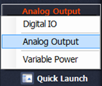
- 1Choose analog output at left menu of front panel.
In Function Generator window, set up Amplitude as , amplitude 50% , Frequency as , Signal as and set up as 1KHz.
Click to output 1KHz 10Vp-p.
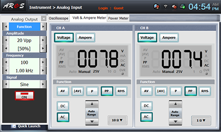
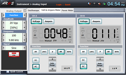
- 2Choose analog input at left menu of front panel.
Choose Volt & Ampere Meter tab and choose , , at CH A and CH B, then the measured value is indicated. Record it in the relevant column of table 1-15. CH A is ER value, and CH B is EX value.
- 3Change the frequency as in table 1-15 to measure and record the result in the relevant column of table 1-15.
Choose quick launch at lower part of left menu of Touch LCD panel and click Analog Output.
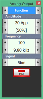
Click at the right of Frequency 100Hz to increase the frequency by 200Hz, and record the measured value indicated at CH A and CH B of Volt & Ampere Meter in the relevant column of table 1-15. (CH A is ER, CH B is Ex)
Measure and record by changing the frequency up to 9.8KHz.
- 4After the measurement, click to cut off the output of function generator.
4. Calculation
1. In table 1-15, calculate the impedance Z with given formula and record the result.