


PART11Blocking Oscillator
Experiment Purpose
- 1.Understands blocking oscillator.
- 2.Understands characteristic of electronic birdcall circuit.
- 3.Understands astable multivibrator.
- 4.Understands LED flickering circuit ad LC resonance circuit.
Experiment 1 :Blocking Oscillator
Theory
When positive feedback occurs at the feedback amplification circuit, the amplification continues without external input, and the oscillation circuit is the circuit that generates electric oscillation using this amplification(feedback oscillation circuit). This is the circuit that gets AC waveform(frequency) from the circuit itself without external input.
Among them, it is a type of non-sinusoidal wave oscillation using the blocking oscillation coil and the transistor.
When the power is supplied at the circuit, the transistor TR1 is forward biased and starts to apply an electric current. The collector current IC flows through the primary winding of the transformer T1 and at the secondary winding, the induced current IO occurs. This charging current IO flows through C2 to the base of TR1, and the increase of base current quickly saturates TR1. When TR1 is saturated, the collector current IC that flows constantly does not generate the induced voltage to the secondary winding. The voltage drop at the secondary winding cuts off TR1 through C2. The reason is – potential is supplied to the base of TR1. The charging of C2 is immediately discharged through R1. When the base of TR1 reaches conducting potential, TR1 is conducted and one period of waveform is completed.
In the circuit, the full line indicates the charging path and the dotted line the discharging path. The discharging time constant is very longer than the charging time constant. The oscillating frequency is determined by R1 and C1 and is expressed as the formula below.

Experiment Process
1. Block a of M11 board, make a connection as in fig.11-2.
2. Make the output power of DC power supplier as 10V and connect it to the circuit.
3. Contact the probe of oscillator to the output(OUT) and observe the output of the oscillator. Check out if the output waveform of the oscillator exists.
4. If there is no output, adjust R3 so that the output waveform can be expressed.
5. Record the output waveform of each measuring point using the oscilloscope in the relevant column of table 11-1.
6. If the value of R1 or C2 decreases, check out how the output waveform changes.
7. Calculate the oscillation frequency to the output waveform, and explain the role of R3 in the oscillator.
tab1Experiment 11-1.1
1.Connection(Block a of M11)
1.Power Connection
Connect between V1 terminal of Variable Power on the left of M11 board and V+ terminal of Block a with red line, and between COM terminal and the earthing terminal with black line.
2.Measuring Instrument Connection
Measuring Waveform of Base and Collector of TR1
On the front panel, connect between A+ terminal of Signal Input CH A and the base terminal of TR1 of Block a on M11 board with red line, and between A- terminal and the earthing terminal of Block a with black line.
On the front panel, connect between B+ terminal of Signal Input CH B and the collector terminal of TR1 of Block a on M11 board with red line, and between B- terminal and the earthing terminal of Block a with black line.
2.Wiring Diagram
flash
3.Measurement
- 1Choose variable power at left menu of Touch LCD panel and set up at 3 CH DC for DC Voltage V1 to become 10V.
Click , and supply the output of DC 10V to the circuit.
Turn on the SW1, 2.
The variable resistance R3 should be located in the middle.
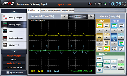
- 2Choose analog input at the left menu of Touch LCD panel, choose Oscilloscope tab to observe the waveform of CH A(base of TR1), CH B(collector of TR1) and draw the result in the relevant column of table 11-1.

- 3To measure the emitter of TR1 and the output(OUT) waveform, make a connection for the measuring instrument as below.
On the front panel, connect between A+ terminal of Signal Input CH A and the emitter terminal of TR1 of Block a on M11 board with red line, and between A- terminal and the earthing terminal of Block a with black line.
On the front panel, connect between B+ terminal of Signal Input CH B and the right terminal of R4(OUT) of Block a on M11 board with red line, and between B- terminal and the earthing terminal of Block a with black line
Observe the waveform of CH A(emitter of TR1), CH B(output(OUT)) at Oscilloscope and draw the result in the relevant column of table 11-1.
- 4After the measurement, choose variable power at left menu of Touch LCD panel, click to cut off the power supply.
Experiment Result Report
1. Experiment Result Table
2. Review and Explanation
1) In the measurement result of table 11-1, calculate the oscillation frequency with the output(OUT) waveform.
2) Calculate the oscillation frequency using the oscillation frequency formula and compare it with the value calculated with the measured waveform above.