


PART1R, L, C Circuit
Experiment 12 :AC Current Measurement
Theory
The current in an electric circuit is like the flow of water in a water pipe. The water flows through the water pipe by the water pressure, and the amount of flowing water can be measured by flowmeter(water gauge), which is put in the middle of the water pipe. Like this, the instrument to measure the amount of current in the electric circuit is the ammeter and this should be put in the middle of the circuit. That is, this should be connected in series to the load to be measured. One difference is that the flowmeter measured accumulated amount of water whereas the ammeter measures the amount of current flowing at the moment.
Like this, the ammeter is the measuring instrument to measure the amount of current flowing through the electric circuit, which should be connected in series to the load to be measured. The internal resistance of ammeter is designed to be very small so when it is connected in parallel to the circuit, it is shorted and huge amount of current flows so that the ammeter is damaged. And when measuring DC circuit, mind the polarities and measuring range, and make sure the needle is not turned by force. When the flowing current is not predicted at all, choose the maximum terminal and measure by lowering the level one by one.
Experiment Process
1. In M01 module, connect as in fig.1-20 using Block a.
2. Connect the output voltage of power supply as AC 12V, measure the current flowing through the series circuit of R5 and R6 and record the result in the relevant column of table 1-12.
tab1Experiment 1-12.1 In M01, compose a circuit as in fig.1-20.
1.Connection
1.Connect the measuring module(ARES-EI-M01) to the platform.
2.Circuit Connection
Connect between upper terminal of R6 at the left of Block c and left terminal of R5 with yellow line.
3.Connection of Power and Measuring Instrument
In M01 module, connect between V1 terminal of Variable Power and mA terminal of Multimeter on front panel with red line, and between Low terminal and right terminal of R5 with red line.
In M01 module, connect between COM and lower terminal of R6 with black line.
2.Wiring Diagram
flash
3.Measurement
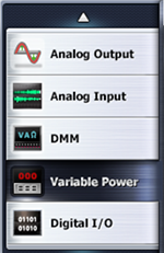
- 1Choose variable power at left menu of Touch LCD panel.
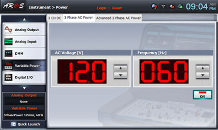
- 2Choose 3 Phase AC DC tab and click at AC Voltage to set up 12V.
Double click AC Voltage, and use Quick Number Keypad, then the number can be entered directly.
- 3Click , then it is as the fig. below, and the output of AC 12V is inputted to the circuit.
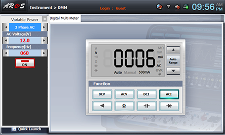
- 4Click dmm at left menu of Touch LCD panel, click , then the current value is indicated. Record it in the relevant column of table 1-12.
- 4After the measurement, click at Variable Power to cut off the power.