PART1R, L, C Circuit
Experiment 9 :Maximum Power Conversion Theory
Theory
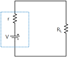
Using Thevenin’s equivalent circuit, DC power can be considered as a circuit in which the battery V and internal resistance r are connected in series as in fig. below. To use the power from this power source, the load resistance RL should be connected as in fig.1-14.
Here, the power delivered to the load PL changes according to the value of load resistance RL, so let’s find out the value of RL that makes P as maximum.

(1)
To find out the maximum value of PL, if PL is differentiated to RL and put as 0,

(2)
Therefore,

(3)
That is, if the load resistance becomes same as internal resistance, the power delivered to the load resistance becomes maximum, and here, the value of maximum power delivered to the load resistance is

(4)
Like this, when the value of load resistance satisfies the condition of maximum power delivery, the circuit is said to become impedance matched. Meanwhile, the total power supplied by the power source, that is, the sum of power PT consumed at internal resistance R and load resistance RL is

(5)
As RL increases, PT does monotone decreasing. Idea power source is the case when the internal resistance R is 0, and here, PL = PT does monotone decreasing as RL increases.
Experiment Process
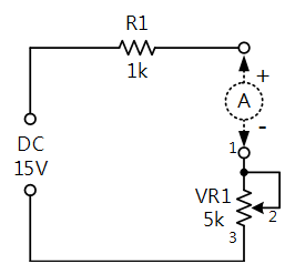
1. In the circuit as in fig.1-15, measure the current flowing to VR1.
Measure by turning the variable resistance to the left end, and turn it gradually to the right and measure the current at the location same as the value of table 1-9 and record the result in the relevant column of table 1-9.
2. Calculate the power value of this circuit. (P = I2 x R)
3. Repeat the experiment above by changing the value of variable resistance VR1 as in table 1-9 and complete the table.
tab1Experiment 1-9.1 In Block a of M01, compose a circuit as in fig.1-15.
1.Connection(M01 Module)
1.Connect the measuring module(ARES-EI-M01) to the platform.
2.Circuit Connection
Connect 1, 2 terminals of VR1 on the left of Block a with yellow lines.
Connect terminal 1 of VR1 on the left of Block a to the left terminal of VR1 with yellow line, and terminal 3 to the right terminal with yellow line.
3.Power Connection
Connect between +15V terminal of Fixed Power and the left terminal of R1 of Block a with red line, and between GND terminal and the left terminal of VR1 with black line.
4.Measuring Instrument Connection
Connect between mA/A of Multimeter and the right terminal of R1 with red line, and between Low terminal and the right terminal of VR1 with black line.
2.Wiring Diagram
3.Current Measurement
- 1If you click dmm at left menu, Digital Multimeter window appears, and if you click , the current value is indicated.
- 2How to Measure the Resistance of VR1
To measure the resistance, the power should be cut off from the circuit. Therefore, pull out the line connected between mA/A terminal and right terminal of R1 and connect it between High terminal and the left terminal of VR1.
When you choose the connected at Digital Multimeter screen, the resistance value is measured. Set up as the relevant column of table 1-9 and measure and record the current.
To measure the current at the setup resistance value, pull out the line connected between High terminal of Multimeter and the left terminal of VR1 and connect it between mA/A terminal and the right terminal of R1.
⑤ Calculate the power value of this circuit. (P = I2 x R)
Power(P) = W
⑥ Repeat the experiment above by changing the value of variable resistance as the table below using the multimeter, and complete the table.
Experiment Result Report
1. Experiment Result Table
2. Review and Explanation
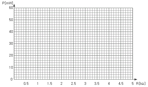
1) Using table 1-9, draw a characteristic curve in the graph below.


