PART6Characteristic of Coil
Experiment Purpose
- 1.Investigate magnetic induction.
- 2.Investigate mutual inductance.
- 3.Investigate magnetic flux detection.
Experiment 1 :Magnetic Induction
Theory
When the current flowing through the coil changes, the magnetic flux changes accordingly so the induced electromotive force occurs by the electromagnetic induction. This is called the magnetic induction. The inductance L of the coil whose number of turns is n becomes L= nΦ/I * [H] when the flowing current is I[A], and the magnetic flux is Φ[Wb] . If there is a change to the magnetic flux that penetrates the coil, the induced electromotive force V, which tries to flow the current in the direction of disturbing the magnetic flux, occurs so it becomes V=- dI/dt=-ndΦ/dt*[V].
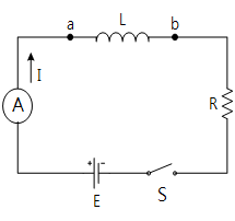
In the circuit in fig.6-2, when the switch is closed in the circuit connecting the coil and the resistance, the scale of ammeter is not constant but increased gradually. On the other hand, when the switch is open, the scale does not become 0 when it is detached and it is decreased quickly. When the switch is closed and stayed for a while, the scale becomes constant.
When the current flows through the coil, the magnetic field changes and the electromotive force is generated in the opposite direction of the magnetic field’s change. This phenomenon is called the magnetic induction. Be careful because bigger electromotive force is generated when opening the switch than closing it.
Experiment Process
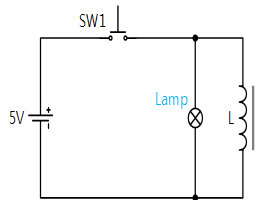
1. In Block a of M06 board, make a connection as in fig.6-3.
2. Apply DC 5V to the circuit, observe the state of lamp when SW1 is pressed and when it is detached, and describe its cause in the relevant column of table 6-1.
- when the switch is pressed:
- when the switch is detached:
tab1Experiment 6-1.1
1.Connection
1.Power Connection
Connect between Fixed Power 5V terminal on the left of M06 board and V+ terminal of Block a with red line, and between GND terminal of M06 board and the earthing terminal with black line.
2.Wiring Diagram
3.Measurement
- 1Observe the state of lamp when SW1 is pressed and when it is detached, and describe its cause in the relevant column of table 6-1.
- when the switch is pressed:
- when the switch is detached:


