


PART1R, L, C Circuit
Experiment 16 :Power of AC Circuit
Theory
A Serbian immigrant, Nikola Tesla(1856~1943) developed AC, a new way of power, while working at DC power plant of Edison. However, Edison was not interested in Tesla’s way of AC power. Edison considered AC power as rival of his DC power so he promised Tesla to give lots of money if he improved DC system. Tesla accepted Edison’s require but Edison did not keep his promise. In the end, Tesla quitted the company and changed the direction of his study to AC power.
DC power causes loss of power when the length of wire. AC power diversifies the current and reduces the resistance so this problem does not occur and same amount of power can be delivered. Therefore, the effect against the cost of AC power is high so that more power plants of AC power can be constructed than those of DC power. The entrepreneur George Westinghouse, who realized the market possibility of AC power, purchased Tesla’s patent on AC motor. Edison tried hard to keep the position of DC power but it got behind AC power. Almost all electricity in the world is provided as AC power of Tesla.
Experiment Process
1. In M01 module, connect as in fig.1-26 using Block a.
2. Adjust the resistance of VR1 as 1kΩ.
3. Set up the output wave form of function generator as sine wave, the output frequency as 1kHz, the output voltage as 20Vpp and make a connection, and measure the voltage applied to both ends of R1, VR1 and record the result in the relevant column of table 1-16.
tab1Experiment 1-16.1 In M01, compose a circuit as in fig.1-26.
1.Connection
1.Connect the measuring module(ARES-EI-M01) to the platform.
2.Circuit Connection
Connect between VR1 on the left of Block a and terminal 1, 2 with yellow line.
Connect between terminal 1 of VR1 and left terminal of VR1 of Block a with yellow line, and between terminal 3 of VR1 and right terminal of VR1 of Block a with yellow line.
Connect between right terminal of R1 and right terminal of VR1 with yellow line.
3.Power Connection
In M01 module, connect between A+ terminal of Function Generator and left terminal of R1 with red line, and between A- terminal and left terminal of VR1 with black line.
4.Measuring Instrument Connection
Voltmeter Connection
Connect between A+ terminal of Signal Input CH A on front panel and left terminal of R1 with red line, and between A- terminal and left terminal of VR1 with black line
Ammeter Connection
Connect between mA/A terminal of Multimeter on front panel and left terminal of R1 with red line, and between Low terminal and the left terminal of VR1 with black line.
2.Wiring Diagram
flash
3.Measurement
- <Resistance Measurement>
1VR1 Resistance MeasurementTo measure the resistance, the power should be cut off from the circuit.
Therefore, remove the yellow line connected between 5k VR1 terminal and left terminal of VR1 of Block d.
Connect between High terminal of multimeter and left terminal of VR1 of Block a with red line, and connect between Low terminal and right terminal of VR1.
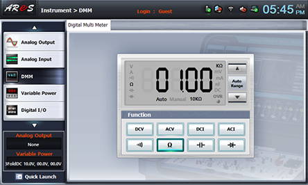
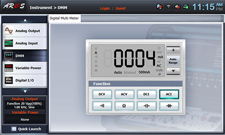
When you choose dmm at left menu of Touch LCD panel, Digital Multimeter window appears, and if you click , the resistance value is indicated. Turn the handle to make 1kΩ.
- 2Combined Resistance Measurement
Connect between left terminal of R7 and that of VR1 with yellow line, between High terminal of multimeter and right terminal of R7 of Block a with red line, and connect between Low terminal and right terminal of VR1.
Click dmm at left menu of Touch LCD panel, measure the combined resistance value and record the result in the relevant column of table 1-16.
Remove the yellow line connected between left terminal of R7 and that of VR1 and remove the line connected to multimeter, and connect between 5k VR1 and left terminal of VR1 of Block a with yellow line.
- <Voltage and Current Measurement>
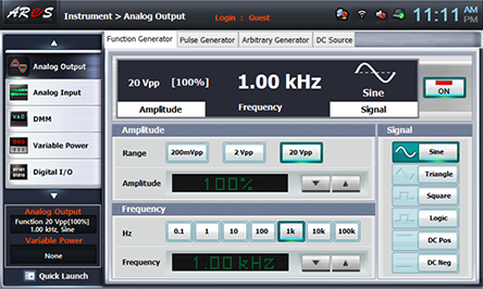
1Choose analog output at left menu of front panel.In Function Generator window, set up Amplitude as , Frequency as , Signal as and click to output 1KHz 20Vp-p.
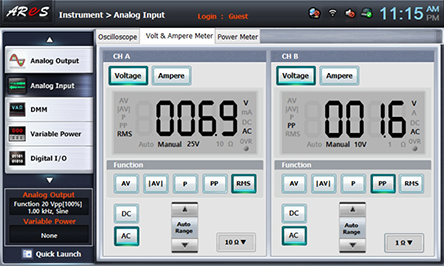
- 2Click analog input at left menu of Touch LCD panel, then Oscilloscope window appears, then choose Volt & Ampere Meter tab and click v at CH A, and then the voltage value of R1, VR1’s both ends is indicated.
Record this value in the relevant column of table 1-16.
- 3Click dmm at left menu of Touch LCD panel and click , then the current value is indicated. Record this value in the relevant column of table 1-16.
- 4Using <Resistance Measurement>, change the resistance of VR1 as 200Ω to execute the measurement process above, and record the result in the relevant column of table 1-17.
- 5After the measurement, click at Variable Power to cut off the power.