


PART7Basic Circuit of Semiconductor
Experiment 5 :Characteristic of LED
Theory
Characteristic of LED: LED is jointed with materials which are easy to emit light such as gallium arsenide(GaAs) and gallium phosphide(GaP), and if forward voltage is applied to this diode, the electron and the electron hole are connected again and emit lights of green, red and yellow.
Identification of Polarity: Just as the diode, LED should be soldered with correct polarity in order for the light to be emitted. If the polarity is connected in the opposite direction, the light is not emitted. LED has two lead wires. One among these is shorter than the other, and this short one is N type semiconductor and means cathode(K). The shorter leg checks the inside of LED(LED is transparent so the inside is visible). Then, the leg part is shows as the fig. on the left. Here, 90% is (+) polarity and 10% is (-) polarity. And finally, the polarity can be identified with the tester.
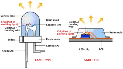
Composition of LED
The current flows in only one direction at the diode and when the current flows, both ends of the diode basically show the characteristic of constant voltage. That is, it means that unlike the resistance, where the voltage drop that is proportional to the current occurs, constant voltage drop occurs at the diode regardless of the amount of the flowing current. Therefore, in the current-voltage graph of the diode, the current rarely flows when the voltage increases from 0 to certain level, and when it is over the level, the current increases almost vertically. This is similar to the short occurred with small voltage applied, and this kind of diode whose characteristic of constant voltage drop is strong is especially called a switching diode
Of course, there is a small voltage increase at the actual diode as the current increases and if the current increases over certain level, the element is damaged by overheating.
LED is the abbreviation for Light Emitting Diode.
As seen in the name, LED is originally a diode that emits the light. Therefore, although weaker than that of switching diode, the characteristic of diode that the voltage drop is irrelevant to the current remains at LED, and the brightness of the light is proportional to the flowing current. In the specifications of LED, the current and the voltage are indicated at the same time as certain mA per certain V. Varying with the manufacturers, but red LED is operated under the voltage of 1.6V while blue or white LEDs are operated under 3.5V, with the rated current of 20mA. Here, the rated current means the current at which the performance of the element is demonstrated in maximum and the stability is guaranteed in successive operations.
As mentioned above, LED has the characteristic of diode so if the voltage slightly higher than rated operation voltage is applied, overcurrent flows and it can be damaged. For example, if the voltage of 3.2V is applied to the LED of 3V 20mA, the current much bigger than the rated current flows and the LED is damaged.
In the actual case, the switching characteristic is too weak at the LED so as the current increases, LED can reach the voltage that is bigger than that of switching diode, and connecting 3.2V to 3V does not easily damage it. However, this is not recommended since the basic characteristic of diode is ignored, and could be thinkable after going through enough reliability tests by the experts.
Instead, it is standard to connect the resistance in series at LED. For example, to operate LED of 3V 20mA with 5V power, the voltage exceeding the rating is 2V, so to bear the extra 2V voltage with 20mA current, the resistance of R=2V/20mA=100 ohm is connected in series and used.
Technically speaking, this resistance plays the role of trans-conductance that changes the voltage source to the current source. For example, when the power voltage at the both ends of LED + serial resistance changes, the voltage of LED is nearly constant and only the voltage at the both ends of serial resistance changes and the current changes accordingly so brightness of LED can be controlled.
Experiment Process
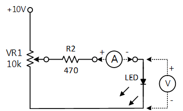
1. To experiment the characterstic of LED, compose a circuit as in fig.7-21 using Block a of M07.
2. Adjust the input voltage by using the current measurement function of separate digital multimeter so that the current flowing thorugh LED becomes 1mA. This current is the forward current (IF) flowing through the diode.
3. Connect DC voltmeter at both ends of LED, measure LED voltage according to the forward current change in table 7-9 and record the result in the relevant column.
tab1Experiment 7-5.1 Measurement of LED Characteristic
1.Connection(Block a of M07)
1.Circuit Connection
In Block a, connect between the left terminal of R1 and center(middle) terminal of VR1 with yellow line.
2.Power Connection
Connect between Variable Power V1 terminal of M07 board and upper terminal of VR1 of Block a with red line, and between COM terminal and the earthing terminal with black line.
3.Measuring Instrument Connection
Ammeter Connection
Measure by using the current measurement function of separate digital multimeter.
Measuring the current (IF) flowing to LED: Connect the red line of digital multimeter to the right terminal of SW1 of Block a and the black line to the upper terminal of LED.
Voltmeter Connection
Measuring input voltage: In Block a, connect between the left terminal of resistance R2 and A+ terminal of Signal Input CH A on front panel with red line, and between the earthing terminal and A- terminal with black line.
Measuring voltage (VF) between LED’s both ends: In Block a, connect between the upper terminal of LED and B+ terminal of Signal Input CH B on front panel with red line, and between the earthing terminal and B- terminal with black line.
2.Wiring Diagram
flash
3.Measurement
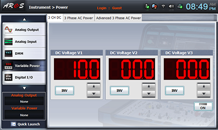
- 1Click variable power at left menu of Touch LCD panel and choose 3 CH DC tab.
At DC Voltage 1, click on the right to become .
Click and apply the output of DC 10V to the input of Block a.
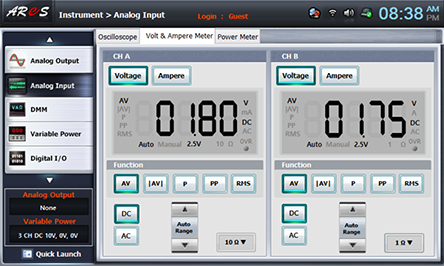
- 2Choose analog input at left menu of Touch LCD panel and click Voltage & Ampere Meter tab.
Click , , at CH A and CH B.
- 3Adjust VR1 and when it is the forward current value indicated at the separate digital multimeter as in table 7-9, record the input voltage(CH A) measured at Voltage& Ampere meter and the voltage between both ends of LED(CH B) (VD) in table 7-9.
- 4After the measurement, click to cut off the output.
Experiment Result Report
1. Experiment Result Table
2. Review and Explanation
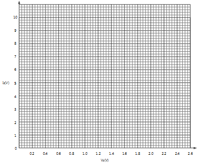
1) Draw I-V characteristic curve using table 7-9.
2) Calculate the voltage drop of R2 resistance 470 using the current flowing through the LED and calculate the total voltage.
VR =470 x IF , VT =VR +VF