


PART1R, L, C Circuit
Experiment 4 :DC Current Measurement
Theory
Generally, ammeter is composed of a meter and a shunt connected in parallel to the meter. The sensitivity of meter is usually 50μA ~ 1mA(FS) and its internal resistance is generally 100Ω ~ 1KΩ (Under same current sensitivity, smaller Rm is better). Also, the shunt used for measuring high current (over 10A) displays its capacity(A) and the output voltage for the connection of the meter. When the input current is IT, the current flowing through the ammeter is Im, and the current flowing through the shunt is Is, IT=Im+Is. And if the internal resistance of ammeter is Rm, and the resistance value of the shunt is Rs, Im and Is have the relational expression below.
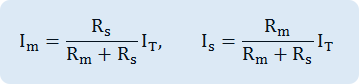
Therefore, the ammeter indicates Im value and the actual measured current can be earned by multiplying the magnification of range.
Experiment Process
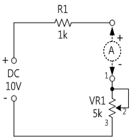
1. In a circuit as in fig.1-5, measure the current flowing to VR1.
Measure by turning the variable resistance to the left end and turn it little by little to the right to measure the current at the location of [%] in table 3-3, and record the result in the relevant column of table 3-3.
2. Measure the resistance value of VR1 at the location of [%] in table 1-3.
tab1Experiment 1-4.1 In Block a of M01, compose a circuit as in fig.1-5.
1.Connection(M01 Module)
1.Connect the measuring module(ARES-EI-M01) to the platform.
2.Circuit Connection
Connect 1, 2 terminals of VR1 on the left of Block a with yellow lines.
Connect between terminal 1 of VR1 on the left of Block a and the left terminal of VR1 with yellow line, and between terminal 3 and the right terminal with yellow line.
3.Power Connection
Connect between V1 terminal of Variable Power and the left terminal of R1 in block a with red line, and between COM terminal and the right terminal of VR1 with black line.
4.Measuring Instrument Connection
Connect between mA/A terminal of multimeter and the right terminal of R1 with red line, and between Low terminal the left terminal of VR1 with black line.
2.Wiring Diagram
flash
3.Measurement
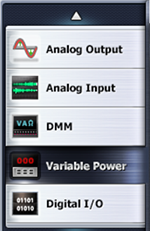
- 1Choose variable power at left menu of Touch LCD panel.
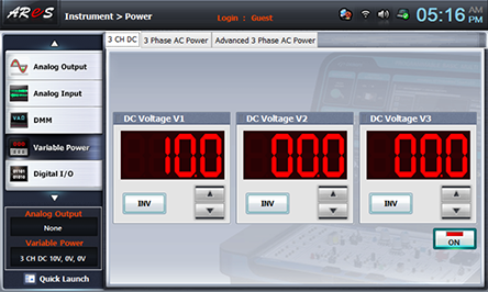
- 2Choose 3 CH DC tab and click at DC Voltage V1 to set up 10V.
- 3Click , and then the output of DC 10V is inputted to the circuit.
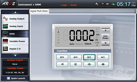
- 4Click dmm at left menu, then Digital Multi Meter window appears. If you click here, the current value is displayed.
- 5How to Measure the Resistance of VR1
To measure the resistance, the power should be cut off from the circuit. Therefore, pull out the line connected between mA/A terminal and right terminal of R1 and connect it between High terminal and the left terminal of VR1. (Refer to the wiring diagram.)
Wiring Diagram
flash
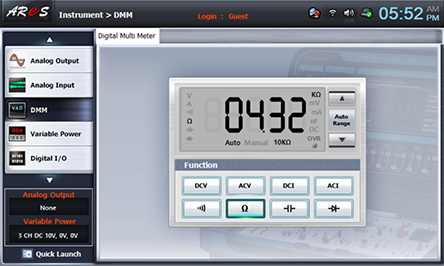
When you choose the connected at Digital Multimeter screen, the resistance value is measured. Record it in the relevant column of table 1-3.
- 6Connect again as in Connection 4) and change VR1 as [%] of table 3-3 to measure the current flowing through VR1. Measure the resistance value of VR1 as in 5) above and record the result in the relevant column of table 1-3.