PART10Characteristic Circuit of Electric Element
Experiment 3 :Temperature Control Circuit
Theory
All materials can be categorized as electrolysis conductor and electron conductor according to the type of electric conduction, and here, the electron conductor can be categorized as metal, semiconductor, and insulator according to the conductivity. The difference of electric conduction between these three materials is determined by the number of free electrons related to the electric conduction within these materials. The number of free electrons within the semiconductor is in the middle of that of the metal and that of the insulator, so the conductivity is also in the middle of both materials.
Besides, the temperature coefficient of the resistance of the semiconductor is very big. The thermistor is the element that uses the fact that the temperature coefficient of semiconductor’s resistance is very big. This thermistor element has very simple principle or structure among various semiconductor elements. The reason that the semiconductor’s resistance decreases according to the temperature rise is because the number of free electrons related to the electric conduction increases with the temperature, and in case of the metal, most of free electrons move freely within the metal so the number of free electrons rarely changes even though the temperature rises. Rather, if the temperature rises, the number of conflicts between free electron and metal ion so the electric resistance increases. Therefore, the temperature coefficient of the metal is positive.
On the other hand, the thermistor is a thermally sensitive resistor whose resistance value changes radically according to the temperature change. Therefore, whether the temperature coefficient is negative(-) or positive(+), it can be called as a thermistor.
The basic resistance-temperature(R-T) characteristic of the thermistor is as below.

RT : resistance value at absolute temperature(T0)(25℃)
β : substance constant K, usually 1000~5000K
ε : basic value of natural logarithm, 2.718
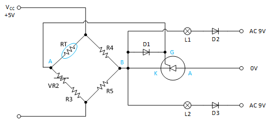
Fig.10-4 is a circuit that uses the characteristic of thermistor. The temperature control switch circuit is composed of a resistance bridge, SCR, lamp and so on. The resistance bridge circuit is composed of a thermistor, and resistances VR2, R3 and R4. The output between A and B of resistance bridge is provided as the triggering voltage of SCR gate. Two lamps are controlled by SCR.
As previously mentioned at the bridge circuit, the formula  is established, and if the bridge circuit is balanced, the output voltage VAB is 0. SCR and the lamp do not be operated. If the temperature increases, the resistance value of RT decreases, and the bridge circuit becomes unbalanced so (+) output voltageVAB operates SCR. Then AC current flows to both lamps through SCR. The diode D1 is operated as a protection diode through which negative(-) VAB voltage passes. VR2 is used to set up the balance of resistance bridge at certain temperature such as ordinary temperature.
Experiment Process
1. Use the thermistor element in Block b of M10 board.
2. Use the multimeter and measure the thermistor resistance value(RT) at room temperature.
3. Hold the thermistor with the thumb and the index finger, and record the change of resistance value indicated at the ohmmeter in the relevant column of table 10-3.
4. Increase the temperature of the thermistor using an electric iron of 25W~30W, and record the change of resistance value indicated at the ohmmeter in the relevant column of table 10-3.
5. Increase the temperature of the thermistor until the resistance value reaches constant value, detach the electric iron from the thermistor and measure and record the resistance value of the thermistor.
tab1Experiment 10-3.1 Experiment for Thermistor Characteristic
1.Connection(Block b of M10)
1.Measuring Instrument Connection
Connect between High terminal of Multimeter on front panel and V+ terminal of Block b on M10 board with red line, and between Low terminal and lower terminal of RT with black line.
2.Wiring Diagram
3.Measurement
- 1Choose dmm at left menu of Touch LCD panel and click .
Record the measured resistance value of the thermistor in the relevant column of table 10-3.
Increase the temperature of the thermistor using hands and observe and record the resistance value of the thermistor.
Increase the temperature of the thermistor using an electric iron of 25W~30W, and record the change of resistance value indicated at the ohmmeter in the relevant column of table 10-3.
Increase the temperature of the thermistor until the resistance value reaches constant value, detach the electric iron from the thermistor and measure and record the resistance value of the thermistor.


