PART4Characteristic of Magnetic Field
Experiment Purpose
- 1.Investigate the characteristic of electromagnetic field.
- 2.Investigate Ampere’s law.
- 3.Investigate the direction of magnetic field and the flow of current.
Experiment 1 :Ampere’s Law
Theory
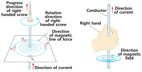
When the current flows through the conducting wire, the line of magnetic force is generated around the wire and Ampere’s law defines its direction. That is, if the direction of current flowing through the conducting line is supposed as the screw-in direction, then the line of magnetic force is generated as a circle in right-handed screw direction.
① Right-handed Screw’s Rule: when the right-handed screw proceeds in the direction of the current, the direction to which the screw is turned is the direction of magnetic field.
② Ampere’s Law: if you put the thumb of the right hand in the direction of the current and wind the conducting wire with the remaining four fingers, the direction of four fingers becomes the direction of magnetic field.
③ When the direction of current flowing through the conducting wire is changed, the direction to which N pole of magnetic needle points is reversed. This is because the direction of magnetic field changes as that of the current changes.
Experiment Process
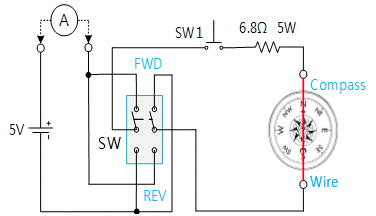
1. In Block a of M04 board, make a connection as in fig.4-3 and locate SW at FWD.
2. Apply DC 5V to the circuit, describe the direction of the compass when SW1 is pressed, and record the measured value of ammeter in the relevant column of table 4-1.
(The pressed time should not be too long.)W
- Describe the direction of flowing current based on the direction of the compass.
3. . Describe the direction of the compass when SW is reversed(REV) and record the measured value of ammeter in the relevant column of table 4-1.
4. Based on the experiment above, describe in which direction the magnetic field is generated when the current flows.
5. In Block b of M04 board, make a connection as in fig.4-3 and execute the process 2~4 above.
- Do the direction of deflection between two compasses correspond?
- Also, do the angle of deflection between two compasses correspond?
Experiment 4-1.1
1.Connection
1.Power Source and Measuring Instrument Connection
Connect between Fixed Power 5V terminal on the left of M04 board and mA/A terminal of multimeter on front panel with red line, and between Low terminal and V+ terminal of Block a with red line.
Connect between Fixed Power GND terminal on the left of M04 board and the earthing terminal with black line.
2.Wiring Diagram
3.Measurement
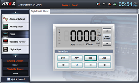
- 1Click dmm at left menu of Touch LCD panel, then Digital Multimeter window appears, and if you click here, the current value is indicated.

- 2Click SW1 and measure the current value indicated at DMM, and record the direction of deflection to which the compass points in the relevant column of table 4-1.
Measure the current value when SW is reversed(REV) and record the direction of deflection to which the compass points in the relevant column of table 4-1.
- 3Measure Block b with 2. Wiring Diagram and 3. Measurement above and record the result in table 4-1.
Wiring Diagram
Experiment Result Report
1. Experiment Result Table
2. Review and Explanation
1) In table 4-1, describe in which direction the magnetic field is generated when the current is flowing.
- In the result of Block b in table 4-1, do the direction of deflection between two compasses correspond? Do the angle of deflection between two compasses correspond? Describe the result.


