PART8Basic Electrical Circuit
Experiment 3 :Constant Voltage Circuit
Theory
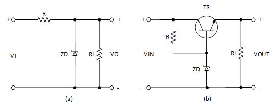
Fig.8-18(a) shows a constant voltage circuit using zener diode. The zener voltage VZ is fundamentally maintained constant to wide range of the current. The effect is changed as the resistance value RR =VZ / I in order to compensate for the change of input voltage VI or the load current. Diode continues to adjust till the circuit condition that the zener current requires which falls to the knee range of diode I-V characteristic curve. The power loss rate is determined by restricting the maximum value of zener diode current.
Pmax=IZM VZ
Experiment Process
1. Make a connection as in fig.8-19 (a).
2. Make a connection by setting up the input voltage as DC 8V, and record the output voltage when VR2 is minimum(1kΩ) and the input voltages are 8V, 12V, 10V in the relevant columns of table 8-3.
3. Record the ouput voltage when VR2 is maximum(0Ω) and the input voltage is 10V in athe relevant column of table 8-3.
4. Make a connection as in fig.8-19 (b).
5. Make a connection by setting up the input voltage as 10V and make VR2 as minimum(1kΩ).
- Measure and record the voltage applied to zener diode.
- Measure and record the voltage between B and E of TR4.
6. Change the input voltage and VR2 as in table 8-3, and measure and record the output voltage in the relevant column.
tab1Experiment 8-3.1 Constant Voltage Circuit Experiment (In Block c of M07, compose a circuit as in fig.8-19.)
1.Connection(Block c of M08)
Zener Diode Constant Circuit Experiment
1.Circuit Connection
In Block c of M08 board, connect between the upper terminal of zener diode(ZD) and the terminal connected to the emitter of TR4 with yellow line.
2.Power Connection
Connect between V1 terminal of Variable Power on the left of M08 board and V+ terminal of Block c with red line, and between COM terminal and the earthing terminal with black line.
3.Measuring Instrument Connection
Connet between High terminal of Multimeter on front panel and the upper terminal of R8 of Block C on M08 board with red line, and between Low terminal and the earthing terminal with black line.
2.Wiring Diagram
3.Measurement
- 1Choose variable power at left menu of Touch LCD panel and set up at 3 CH DC for DC Voltage V1 to become 8V.s
Click , and supply the output of DC 8V to the circuit.
Turn on the SW3.
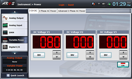
- 2When VR2 is minimum(1kΩ), choose dmm at left menu of Touch LCD panel, click and record the measured value in the relevant column of table 8-3.
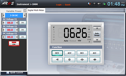
Record the output voltages when the input voltages are 8V, 12V, 10V in the relevant columns of table 8-3.
Record the output voltage in the relevant column of table 8-3 when VR2 is maximum(0Ω) and the input voltage is 10V.
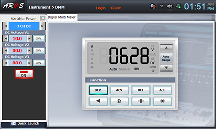
Transistor, Zener Diode Constant Circuit Experiment
1.Connection
1.Circuit Connection
In Block c of M08 board, connect between the upper terminal of zener diode(ZD) and the terminal connected to the base of TR4 with yellow line.
2.Power Connection is same as 1. Connection> 2) Power Connection.
3.Measuring Instrument Connection is same as x1. Connection> 3) Measuring Instrument Connection.
2.Wiring Diagram
3.Measurement
- 1Choose variable power at left menu of Touch LCD panel and set up at 3 CH DC for DC Voltage V1 to become 10V.
Click , and supply the output of DC 10V to the circuit.
Turn on the SW3.
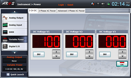
- 2Make VR2 as minimum(1kΩ).
- 3Measure the voltage between both ends of zener didoe(ZD) and record the result in the relevant column of table 8-4.
Choose dmm at left menu of Touch LCD panel, connect the red lead wire connected from Multimeter High terminal to the upper terminal of R8 to the upper terminal of ZD and record the measured value.
- 4Measure and record the voltage between B and E of TR4.
Connect the red lead wire connected from Multimeter High terminal to the upper terminal of R8 to base terminal of TR4, and connect the black lead wire connected to the earthing terminal to the upper terminal of R8 and record the measured value.
- 5Change the input voltage and VR2 as in table 8-4, and measure and record the output voltage in the relevant column.
- 6After the measurement, choose variable power at left menu of Touch LCD panel and click to cut off the power supply.
Experiment Result Report
1. Experiment Result Table
Voltage between both ends of ZD : (V)
Voltage between B-E of TR4 : (V)


