


PART9Electrical Acoustic Amplification Circuit
Experiment Purpose
- 1.Understands push-pull amplification circuit.
- 2.Understands characteristic of wheatstone bridge.
- 3.Understands acoustic control circuit.
Experiment 1 :Push-Pull Amplifier
Theory
Power amplifier means the circuit that amplifies electric energy so that it can be changed as sound through the speaker, and push-pull circuit is used frequently.
In fig.9-2, when the input AC signal (Vg) is applied, the voltage is induced at the secondary part of input transformer(IPT). The upper voltage among the induced voltage on the secondary part of IPT is applied as forward direction to Q1 transistor and the amplified collector current flows through the output transformer(OPT). The lower voltage among the induced voltage on the secondary part
reverse direction to Q2 transistor and maintains the cutoff state. When the input AC signal(Vg) is applied in reverse direction, the voltage in the opposite direction of the arrow is induced at the secondary part of input transformer(IPT). When the reverse voltage is applied to two transistors, Q1 transistor is cut off in reverse direction, but Q2 transistor becomes forward direction so the amplified collector current flows through the output transformer.
During one period while (+) signal and (-) signal enters through the transformer, Q1 and Q2 operate in turn and the output current penetrates upward and downward the primary part of output transformer. At the secondary part of output transformer, full one period AC signal is completed and this operates the speaker and makes sound.
Fig.9-3 is a double ended push-pull amplifier which operates as AB level push-pull circuit. The voltage distributor is composed of base bias resistances R10 and R11, and small flow of current of two transistors TR2 and TR3 in stop state is supplied as standby bias to the base. The emitter resistance R12 is used to compensate for small difference between two transistors and to stabilize the operation of the circuit.
TR1 is A level common emitter amplifier, which is used to amplify the input signal and output it to T1. The input transformer T1 including center tab coil operates the phase splitting. The signal induced to the secondary coil is same as the amplitude but has the phase difference of 180 degree. Therefore, if the input is sine wave, TR2 and TR3 operate in turn. The output signal is combined at the speaker by the output of the output transformer T2.
Experiment Process
1. Using Block b of M09, make a connection as in fig.9-3.
2. Make the power of power supplier as DC 9V and connect to the circuit.
- Turn on SW1, 2, 3, 4.
3. Adjust the function generator to make the output waveform as sine wave, and connect it to the input terminal.
- Change the frequency of function generator and observe the sound of the speaker. Check out if the sound changes according to the change of the frequency.
4. Set up the input frequency as 1kHz 200mVpp.
- Observe the waveform of OPT input terminal and draw it in the relevant column of table 9-1.
- Observe the input and output waveforms and draw it in the relevant column of table 9-1.
5. Connect the bypass capacitor(connect C3 and R8 in parallel using the connection line), and observe the change of sound outputted from the speaker.
- Observe the waveform of OPT input terminal and draw it in the relevant column of table 9-1.
- Observe the input and output waveforms and draw it in the relevant column of table 9-1.
tab1Experiment 9-1.1
1.Connection(Block b of M09)
1.Power Connection
Connect between V1 terminal of Variable Power on the left of M09 board and V+ terminal of Block b with red line, and between COM terminal and the earthing line with black line.
2.Measuring Instrument Connection
Function Generator Connection
Connect between A+ terminal of Signal Output on front panel and the left terminal(Input) of C1 of Block b on M09 board with red line, and between A- terminal and the earthing line with black line.
Voltmeter Connection
Connect between A+ terminal of Signal Output CH A on front panel and the upper terminal of T2(OPT) of Block b on M09 board with red line, and between A- terminal and the earthing line with black line.
Connect between B+ terminal of Signal Output CH B on front panel and the lower terminal of T2(OPT) of Block b on M09 board with red line, and between B- terminal and the earthing line with black line.
2.Wiring Diagram
flash
3.Measurement
- 1Choose variable power at left menu of Touch LCD panel and set up at 3 CH DC for DC Voltage V1 to become 9V.
Click , and supply the output of DC 9V to the circuit.
Turn on the SW1, 2, 3, and 4.
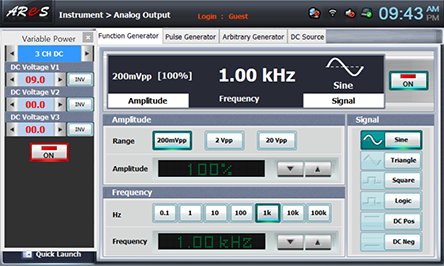
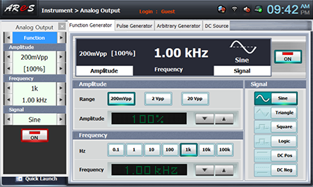
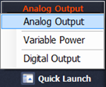
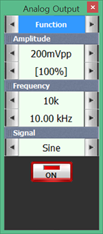
- 2) Choose analog output at left menu of front panel, click Function Generator and set up Amplitude Range as , Frequency as , Signal as and click to output 1kHz 200mVpp.
Change as random frequency(100Hz~15kHz) and observe the speaker’s sound change.
Click quick launch , change as random frequency(100Hz~15kHz) in Analog Output and observe the speaker’s sound change.
- 3OPT Input Waveform Measurement
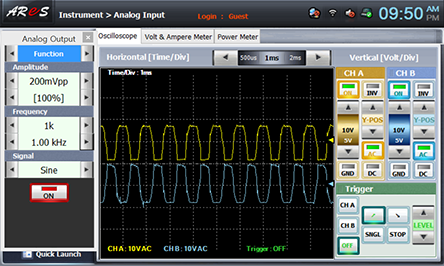
Set up the input frequency of the function generator’s output as 1kHz 200mVpp and choose analog input at the left menu of Touch LCD panel, choose Oscilloscope tab to observe the waveform of OPT input terminal and draw it in the relevant column of table 9-1.

The waveform of CH A is TR2 base input waveform and that of CH B is TR3 base input waveform. Draw each waveform in the relevant column of table 9-1.
- 4Input/Output waveform measurement
Change the connection of red line from A+ terminal of Signal Input CH A on front panel to SW2 terminal of Block b on M09 board from A+ terminal to the left terminal(Input) of C1.
Change the connection of red line from B+ terminal of Signal Input CH B on front panel to SW3 terminal of Block b on M09 board from B+ terminal to the speaker output terminal(Output).
Wiring Diagram
flash
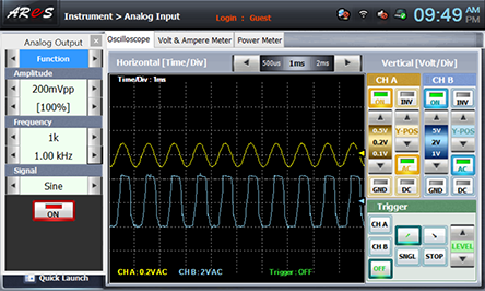
In Oscilloscope, the waveform of CH A is input signal waveform and that of CH B is output waveform. Draw each waveform in the relevant column of table 9-1.

- 5Measuring by connecting bypass capacitor
In the circuit of Block b, connect between the upper terminal of C3 and the upper terminal of R8 with yellow line and execute the measurement process 2)~4) above and record the result in table 9-1.
- 6After the measurement, choose variable power at left menu of Touch LCD panel, click to cut off the power supply, and click at analog output to cut of the function generator.