


PART10Characteristic Circuit of Electric Element
Experiment 2 :Experiment for Lighting Control Switch Circuit
Experiment Process
1. Using Block a of M10 board, make a connection as in fig.10-3.
2. Make the output power of DC power supplier as 6V.
3. Turn VR1 to turn on LED1. Measure and record the voltages on A, B, C points.
4. Measure and record the voltages on A, B, C points while shading CdS window with hands.
tab1Experiment 10-2.1
1.Connection(Block a of M10)
1.Power Connection
Connect between V1 terminal of Variable Power on the left of M10 board and V+ terminal of Block a with red line, and between COM terminal and the earthing line with black line.
2.Measuring Instrument Connection
Connect between High terminal of Multimeter on front panel and the base terminal of TR1 of Block a on M10 board with red line, and between Low terminal and the earthing terminal of Block a with black line.
2.Wiring Diagram
flash
3.Measurement
- 1Choose variable power at left menu of Touch LCD panel and set up at 3 CH DC with for DC Voltage V1 to become 6V.
Click , and supply the output of DC 6V to the circuit.
Turn on the SW1.
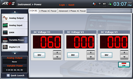
Turn VR1 and turn on LED1.
- 2Choose dmm at the left menu of Touch LCD panel and click .
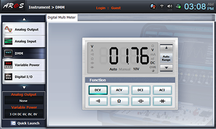
Record the measured value(VA point) in the relevant column of table 10-2.
Plug out the red lead wire connected between High terminal of Multimeter on front panel and the base terminal of TR1 of Block a on M10 board and change the connection to the base of TR2(VB point), the emitter of TR2(VC point) and measure the voltage and record the result in the relevant column of table 10-2.
- 3Execute the process 2) above while shading CdS with hands and record the result in the relevant column of table 10-2.
- 4After the measurement, choose variable power at the left menu of Touch LCD panel and click to cut off the power supply.