


PART2Electric Magnetic Circuit
Experiment Purpose
- 1.Understand electric magnetic devices.
- 2.Understand the characteristic of magnetic field.
- 3.Understand the electromagnet.
Experiment 1 :Magnetic Experiment
Theory
* Magnetic force: the force that is working between two magnets or between the magnet and a piece of metal.By tying the middle of two magnets with strings and making two same polarities or two ⇒ ⇒ ⇒ different polarities become nearer, find out if one specific force is working.
ㆍ Attractive force: a pulling force between two different polarities(between N pole and S pole)
ㆍ Repulsive force: a pushing force between two same polarities(between N pole and N pole, between S pole and S pole)
* Magnetic field: the area that magnetic force reaches
⇒ Put iron dust or small piece of iron near or far from the magnet and observe its attracted shape
ㆍIntensity of magnetic field: the size of force that N polar of magnetic needle receives in the magnetic field. The nearer it is to the magnetic pole.
ㆍDirection of magnetic field: the direction to which N pole of magnetic needle points when the magnetic needle is put within certain location of magnetic field(it comes out from N pole and goes into S pole)
▶Line of magnetic force: the line that links the direction of magnetic field continuously
⇒ Put a number of compass around the magnet and draw the curve that links continuously the direction of N pole
ㆍIt comes out from N pole and goes into S pole.
ㆍThe line of magnetic force does not cross or split.
ㆍThe denser the line of magnetic force is, the stronger the magnetic force is.
▶Terrestrial magnetism : When you put a compass on the Earth, the N pole points to the north, and S pole to the south. This is because the earth plays the role of one big magnet and this phenomenon is called the terrestrial magnetism.
ㆍS pole of terrestrial magnetism: it is located near the Arctic.
ㆍN pole of terrestrial magnetism: it is located near the Antarctic.

Experiment Process
1. Magnet Experiment
- Put the magnet near Block a. Is N pole attached? Or S pole?
2. Reed SW Exercise
In M02 board, measure the resistance between reed switch’s both ends of Block b using the multimeter as in fig.2-4.
Draw near the magnet to reed switch and measure the resistance again using the multimeter. Record the result in the relevant column of table 2-1. How is it different when there is a magnet and when there is not?
tab1Experiment 2-1.1
1.Connection
1.Measuring Instrument Connection
Connect bewteen High terminal of multimeter on front panel and left terminal of REED SWITCH of Block b with red line, and between Low terminal and right terminal of REED SW with black line.
2.Wiring Diagram
flash
3.Measurement
- 1Click dmm at left menu of Touch LCD panel, then Digital Multimeter window appears, and if you click here, the resistance value is indicated.
- 2Measure the resistance value with the magnet being detached from REED SW and record the result in table 2-1.
- 3Measure the resistance value with the magnet being near to REED SW and record the result in table 2-1.
Experiment Process
3. Reed Relay Exercise
In M02 board, make a connection as in fig.2-5 using Block c.
Apply +5V, turn on the switch and measure the resistance of switch using the ohmmeter of multimeter and record the result in table 2-1.
Turn off the power switch and measure the resistance again to record in table 2-1. What are the differences between applying and not applying the power?
tab2Experiment 2-1.2
1.Connection
1.On the left of M02 board, connect between Fixed Power 5V terminal and left terminal of REED RELAY of Block c with red line, and between GND terminal and right terminal of REED RELAY with black line.
2.Measuring Instrument Connection
Connect between High terminal of multimeter on front panel and left terminal of REED RELAY SW of Block c with red line, and between Low terminal and right terminal of REED RELAY SW with black line.
2.Wiring Diagram
flash
3.Measurement
- 1Click v at left menu of Touch LCD panel, then Digital Multimeter window appears, and if you click here, the resistance value is indicated. Measure this resistance value and record the result in table 2-1.
- 2Remove the red line connected between Fixed Power 5V terminal on the left of M01 board and left terminal of REED RELAY of Block c and measure the resistance value to record in the relevant column of table 2-1.
Experiment Process
4. Relay Exercise
In M02 board, make a connection as in fig.2-6 using Block d.
Measure the value in the ohmmeter with the output voltage of power supply as 0 and record the result in the relevant column of table 2-1.
Check out the value in the ohmmeter with increasing the output voltage of power supply. Measure the voltage that changes the value of ohmmeter and record the result in the relevant column of table 2-1.
tab3Experiment 2-1.3
1.Connection
1.On the left of M02 board, connect between Variable Power V1 terminal and terminal 4 of Block d with red line, and between COM terminal and terminal 5 with black line.
2.Measuring Instrument Connection
Connect between High terminal of multimeter on front panel and terminal 2 of Block d with red line, and between Low terminal and terminal 3 with black line.
2.Wiring Diagram
flash
3.Measurement
- 1Click dmm at left menu of Touch LCD panel, then Digital Multimeter window appears, and if you click here, the resistance value is indicated. Measure this resistance value and record the result in table 2-1.
- 2Choose quick launch at bottom of left menu on front panel and click Variable Power .
- 3Choose 3 CH DC tab and click , then DC output is applied to the circuit.
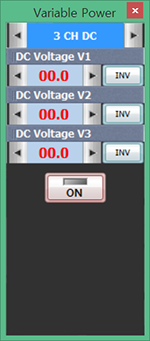
Click at DC Voltage V1 to increase the voltage and measure the resistance value to record the result in the relevant column of table 2-1.
- 4After the measurement, click to cut off the voltage applied to the circuit.
Experiment Process
5. SSR(Solid State Relay) Exercise
In M02 board, make a connection as in fig.2-7 using Block e.
Connect the power supply between terminal 3-4, increase the power gradually and measure the resistance value of ohmmeter connected between terminal 1-2, measure the voltage at which the resistance value is changed and record the result in the relevant column of table 2-1.
tab4Experiment 2-1.4
1.Connection
1.Power Connection
On the left of M02 board, connect between Variable Power V1 terminal and terminal 3 of Block e with red line, and between COM terminal and terminal 4 with black line.
2.Measuring Instrument Connection
Connect between High terminal of multimeter on front panel and terminal 1 of Block e with red line, and between Low terminal and terminal 2 with black line.
2.Wiring Diagram
flash
3.Measurement
- 1Click dmm at left menu of Touch LCD panel, then Digital Multimeter window appears, and if you click here, the resistance value is indicated. Measure this resistance value and record the result in table 2-1.
- 2Choose quick launch at bottom of left menu on front panel and click .
- 3Choose 3 CH DC tab and click , then DC output is applied to the circuit.
Click at DC Voltage V1 to increase the voltage and measure the voltage at which the resistance value is changed, and record resistance value in the relevant column of table 2-1.
- 4After the measurement, click to cut off the voltage applied to the circuit.
Experiment Result Report
1. Experiment Result Table
2. Review and Explanation
1) Describe the operational principles of reed switch, reed relay, relay, and SSR.
2) Describe the differences between when voltage is increasing and decreasing, and between on and off with SSR of table 2-1.
3. Discuss the experiment result.
REED SW
Reed switch is operated by magnetic attractive force when N pole and S pole are induced to both reed blades by the coil or permanent magnet. When the magnetic filed is extinct, the contact is recovered by the elasticity of reed blades.
Glass Capsule
In the process of glass forming, the inside of glass is made as vacuum state and inert gas(usually nitrogen) is charged. Within the glass capsule, inert gas is filled to protect the damage of contact, and the contact is plated with rhodium(Rh) or ruthenium(Ru).
Contact Plate
The contact of two reeds is composed of alloy of nickel/iron(52% Nickel). To be affected by the magnetic field, the reed should be ferromagnetic. Ferromagnetic materials are: iron, cobalt, nickel
When the magnet is near to the reed sensor/switch, the device is activated, and when it is removed from around the reed sensor/switch, the device is deactivated.
However, whether the magnetic interaction is related to the activation of reed switch contact or not is not certain. One possibility is that the magnet may stimulate the metal part of reed switch and the attractive force between electric contacts occurs to cause reed switch activation.
The other possibility is that the magnet induces magnetic flux through the electric contact.
When the magnetic flux is high enough, the magnetic attraction becomes the cause to close the reed switch.
The fig. below is a typical example of distance to activate reed switch and reed sensor.
(a) Parallel magnet type
(b) Vertical magnet type
(c) Parallel magnet type
As the fig. above, the magnetic direction and location of reed switch plays an important role to relative distance activation. Also, the size of activation area(lobe) is dependent upon the intensity of magnet and sensitivity of reed switch.
Proper direction of magnet to reed sensor/switch is a very important consideration to satisfying the requirements of application for mechanical system, magnetic intensity, the allowable error of sensitivity of reed switch/sensor.
Reed Relay
Reed relay is, as the fig. below, the integration of reed switch and the coil wound around it and generating the magnetic field. The contact terminal and coil terminal are contacted to each and molded with epoxy resin. The operational principle is as follows: When the electricity is applied to the coil, magnetic attractive force occurs at the overlapping area of two reed plates and they are attached to each other(ON) and when the current is cut off, two reed plates fall apart by their own elasticity(OFF) and recover. There are tubular type, DIP type, SIP type, PC board mounted type, and surface mounted type.
The biggest differences between reed relay and general relay are ①the electric circuit and magnetic circuit are operated by same media(reed plate) ②the switch and the coil are separated so that the operation by permanent magnetic field is possible.
The characteristics of reed relay are as follows. ①small size, light weight ②high speed operation by small power ③the contact is not affected by surroundings ④ the structure is simple and the price is low. The disadvantages of reed relay are as follows. ①it is easy to cause contact welding with ON/OFF of big power ②it is hard to determine the order of operation when multi-contact is composed by putting multiple reed switches to one coil ③the foreign material between the contacts cannot be removed. The actual reed relay is used in case of the capacity under 1~0.5A.
Relay
Relay uses the characteristic that the coil becomes the magnet when the current is flowing. When the coil becomes an electromagnet, it pulls the iron plate and opens or closes the contact of switch attached to the iron plate. The virtue of relay is that it can interlock with electrically independent circuit.

By the operation of the circuit composed of low voltmeter such as that of 5V, the circuit of AC 100V or that of big current can be ON/OFF. The relay opens or closes the contact mechanically so it cannot be operated with high speed generally. There are various types of relay, so proper one should be chosen according to the voltage applied to coil(driving voltage), capacity of contact and so on.
By the contact structure, the relay can be categorized as mechanical relay which opens and closes the electric contact by electromagnetic force(general relay, print-circuit board relay) and semiconductor relay which is composed of semiconductor and does not have mechanical driving part(SSR, MOSFET relay). According to the usage, the relay is categorized as relay for control(power relay) and for communication(signal).
Mini relay
Micro relay
SMD relay
Low power relay
Latching relay
Industrial relay
Power relay
Characteristic of Relay
Recently, cheap and high-performance semiconductor switch has been supplied so the use of relay is decreased. Especially, in terms of speed or power consumption and durability, the relay, which operates the mechanical contact with the coil, is inferior to the semiconductor switch, which has no moving part. However, the virtues of relay compared to semiconductor switch are as follows. It has small ON resistance and big insulation resistance in case of OFF, and it has big internal pressure and current capacity.
This is an example of small relay used in electric circuit. Generally, reed relay is small and has high speed and low power consumption. When using the relay in the electric circuit, the opening and closing is not executed correctly if the load current of the contact is too small.
Depending on the brand, the standard minimum load for the opening and closing is written in the catalogue. Generally speaking, the bigger the current capacity of contact is, the more improper it is for the opening and closing of small electric charge. Do not limit only to the relay and flow tens and hundreds mA current at the mechanical contact such as switch.
Also, if the load voltage is too small, the thermal electromotive force of the contact by the excitation of the circuit can be a problem. The size of thermal electromotive force is usually smaller than 1mA. Specially, there are products whose virtue are low thermal electromotive force.
SSR(Soled State Relay)
While the electromagnetic force operates the magnet relay, SSR is a [noncontact relay] which does not have mechanical contact structure. The switching is executed with it to be resin molded to the case by switching semiconductor element(such as power transistor, SCR or TRIAC). This is a totally solidified electronic switch.
SSR is trustworthy and has a long life than magnet relay, and is endurable to noise(EMI) and shock, is operated by small signal, and has fast response speed. It is proper to be applied in wide area such as industrial machinery and tools, office machinery and tools and so on.
Type
Advantage of SSR
◆ Insulation of Input/Output by Photo Coupler
Photo coupler is used for the electric insulation of SSR input and output. It insulates between the input and the output and cuts of the feedback of the noise on the load side to the input side.
◆ Small Signal Operation
Because of the photo coupler connection, SSR is operated when low voltage, low current is applied to the input signal, so it can be operated directly by DTL, TTL, C-MOS and LINEAR IC.
◆ Low Noise
It has low chattering because it is a noncontact relay, and the inrush current by on, off is small so the effect of noise is small.
◆ Noise :
Noise occurs with the mechanical relay but SSR is a noncontact relay so the noise does not occur.
◆ Shock, Oscillation
The relay is intolerant to shock and oscillation since it is a physical element, but SSR is an electronic component so it is tolerant to shock and oscillation.
◆ Phase Control
In case of contact switching, the mechanical relay involves flame(Arc) and its lifespan is shortened and speed is low, but SSR has high speed of switching so the phase control is possible. (the control of motor speed, brightness of light)
Disadvantage of SSR
◆ Heat
In case of mechanical relay, it reaches high temperature momentarily at switching but once the switching is done, it can be used for a long time so you do not have to consider the thermal design. However, the temperature of SSR rises by the current s o the thermal design is needed.
◆ SSR within the Zero-Cross Circuit Cannot Be Used during Phase Control
In case of phase control, the turn-on time can be delayed for maximum ½ cycle, so the SSR within the Zero-Cross circuit cannot execute phase control. Therefore, non-Zero-Cross type SSR is used.