


PART1R, L, C Circuit
Experiment 6 :Power of DC Circuit
Theory
Fig.1-7 shows a basic current circuit. Here, the ammeter should be connected to the circuit in serial, and the voltmeter to the measuring load in parallel. That the resistance rarely exists means the state to be shorted, and that the resistance is infinite means the state to be opened. Also, if the resistance is connected to the circuit through which the current flows, work occurs and this is called power. The power means the amount of work done within unit time, and the sign is “P” and the unit is W(Watt). If the load has constant resistance, the work is proportional to the square of the potential difference(voltage) between the load’s both ends. If the power is expressed in formula as the relationship between voltage and current, it is as below.
P = V x I, P = V2 / R, P = I2 x R
Experiment Process
1. Connect R1 of Block a as in fig.1-8 and measure the current flowing through the circuit and the voltage of R1’s both ends and record the result in table 1-5.
2. Connect R16 of Block k as in fig.1-8 and measure the current flowing through the circuit and the voltage of R1’s both ends and record the result in table 1-5.
3. Calculate the power of each resistance following the formula and compare it to the measured value.
tab1Experiment 1-6.1 In M01, compose a circuit as in fig.1-8.
1.Connection(M01 Module)
1.Connect the measuring module(ARES-EI-M01) to the platform.
2.Power and Measuring Instrument Connection
Ammeter Connection
Connect between V1 terminal of Variable Power and mA/A terminal of multimeter on front panel with red line, and between Low terminal and the left terminal of R1 of Block a with red line.
Connect between COM terminal of multimeter and the right terminal of R1 with black line.
Voltmeter Connection
Connect between V1 terminal of Variable Power and A+ terminal of Signal Input CH A on front panel with red line, and between A- terminal and the left terminal of R1 with red line.
2.Wiring Diagram
flash
3.Measurement
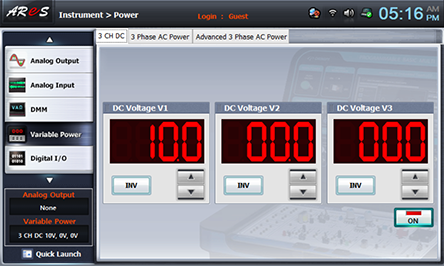
- 1Choose variable power at left menu of Touch LCD panel.
- 2Choose 3 CH DC tab and click at DC Voltage V1 to set up 10V.
- 3Click , and then the output of DC 10V is inputted to the circuit.
- 4Click dmm at left menu, then Digital Multi Meter window appears. If you click here, the current value is displayed.

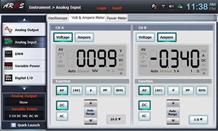
- 5Choose analog input at left menu of Touch LCD panel and click Volt & Ampere Meter tab.
The value indicated at CH A is the measured value of voltage of R1’s both ends. Record it in table 1-5.
- 6Measure the voltage and current flowing through R16 and record it in table 1-5.