PART1R, L, C Circuit
Experiment 3 :Characteristic of Resistance
Theory
Small Carbon Film Resistance
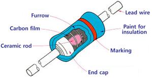

By burning and adding a carbon-resistor to a ceramic rod and cutting a spiral furrow, you can make the resistance value you want. Plug metal caps to which lead wire is attached to both ends, and paint protecting paint for insulation.
Solid Resistance
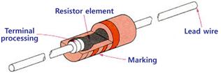

The resistor is a solid resistor and it is molded so the credibility and insulation are high and is strong to the arc.
Metallic Film Resistance(Painted Type)


You can make the resistance that you want by evaporating or sintering metal film to a ceramic rod and cutting a spiral furrow. At both ends, metal cap to which lead wire is attached is plugged in and protection paint for insulation is applied.
Metal Film Resistance
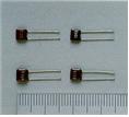
This is made by evaporating the metal to ceramic substrate, forming resistance pattern, attaching lead wire and trimming by laser.
Metal Foil Resistance
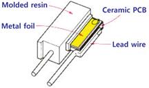

This is made by attaching alloy metal foil to ceramic substrate, attaching the electrode after etching and trimming by laser. To avoid mechanical distortion, thin wire is bonded between lead wire and metal foil.
Metal Oxide Film Resistance
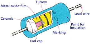

This is made by attaching metal oxide(tin or antimony) to ceramic rod, plugging in a metal cap to which lead wire is attached, and cutting a spiral furrow.
Coil Resistance
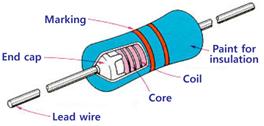

This is made by winding and attaching resistance line(manganese or nichrome) to ceramic rod. The resistance value is determined by the type of line or number of winding.
Cement Resistance
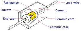

This is made by putting a resistance unit of coil type or metal oxide film type into a ceramic case and covering it with the silicon type cement.
Metal Plate Resistance
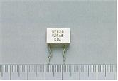
This is made by putting in a resistance unit of metal plate type into a ceramic case and covering it with the silicon type cement.
Porcelain Enamel Resistance
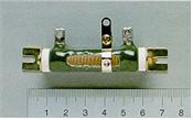
This is made by winding the resistance line to ceramic pipe and covering it with the enamel film.
Experiment Process
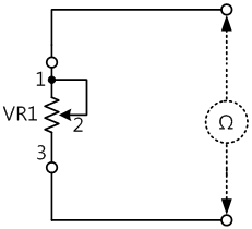
1. Connect VR1 to Block a, and measure with the separate digital multimeter and with the multimeter of AReS the resistance values when it is turned clockwise to maximum, and counterclockwise to minimum, and when it is on the center, and record the measured values in the relevant columns of table 1-2.
tab1Experiment 1-3.1 In Block a of M01, compose a circuit as in fig.1-4.
1.Connection(M01 Module)
1.Connect the measuring module(ARES-EI-M01) to the platform.
2.Circuit Connection
Connect 1, 2 terminals of VR1 on the left of Block a with yellow lines.
Connect terminal 1 of VR1 on the left of Block a to the left terminal of VR1 with yellow line, and terminal 3 to the right terminal with yellow line.
3.Measuring Instrument Connection
Using Separate Digital Multimeter
In M01 module, connect a separate digital multimeter at both ends of VR1 and measure and record the resistance value. Connect the red lead wire to V, Ω terminals and the black lead wire to COM terminal.
Using Multimeter of AReS
Connect between each end of VR1 to High terminal of Multimeter on front panel with red line, and to Low terminal with black line.
2.Wiring Diagram
Resistance Measurement Using Multimeter
Resistance Measurement Using AReS
3.Measurement
- 1Using Separate Digital Multimeter
Locate the measurement choice switch of digital multimeter at Resistance(Ω).
Turn on the power of digital multimeter.
Record the indicated value in the relevant column of table 1-2.
- 2Using Multimeter of AReS
If you click dmm at left menu, Digital Multi Meter window appears and if you click here, the voltage value is displayed. Record it in the relevant column of table 3-2.
- 3Execute process 1)-2) to both ends of VR1 and measure and record the resistance value when VR1 is on the locations below.
when it is tuned clockwise to maximum
when it is tuned counterclockwise to minimum
when it is on the center


