


PART8Basic Electrical Circuit
Experiment 4 :Lighting Circuit
Theory
SCR is applied in power control area such as lamp lighting, electric heater, or electric motor. Power control is done by adjuting the conduction angle of input voltage waveform and controlling the power supplied to the load so it eventually executes the phase control.
Fig.8-20 is an example of a circuit that controls the power using SCR.
SCR plays the role of a switch that discontinuously selects parts of (+) half period of AC voltage and lets the current flow through the lamp. RC circuit determines the parts of (+) half period that is necessary for charging the gate voltage that is enough to conduct SCR to the condenser C4. The power deliverd to the lamp during (+) half period is dependant on the parts of (+) half period that is needed for chaging C4 that operates SCR. The power flowing through the lamp can be changed by changing VR3 and this is called phase control.
SCR is conducted only during (+) half period of input supplied voltage. There are two ways to supply full period of power to the load. One is to supply the input voltage from the output of full-wave rectifier and the other is to connect two SCR in inverse parallel as in fig.8-21.
Experiment Process
1. Make a connection as in fig.8-20 using Block d of M08.
2. Turn VR3 to the right as much as possible, and input AC 9V from the power supplier.
3. Turn VR3 to the left again, then how does the brightness of the lamp change according to the change of VR3?
Measure and record the gate input waveform and voltage and the output waveform and voltage of the lamp’s both ends at the point that the lamp is turned on.
tab1Experiment 8-4.1 Lighting Circuit Experiment (In M08 of Block d, compose a circuit as in fig.8-20.)
1.Connection(Block d of M08)
1.Power Connection
Connect between V1 terminal of Variable Power on the left of M08 board and the left terminal of LP(Lamp) of block d with red line, and between COM terminal and the lower left terminal of C4 with black line.
2.Measuring Instrument Connection
Gate Measurement
Connect between A+ terminal of Signal Input CH A on front panel and the gate terminal of Block d on M08 board with red line, and between A- terminal and lower left terminal of C4 of Block d with black line.
Lamp Load Measurement
Connect between B+ terminal of Signal Input CH B on front panel and the left terminal of LP(Lamp) of block d with red line, and between B- terminal and Anode terminal of SCR with black line.
2.Wiring Diagram
flash
3.Measurement
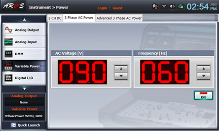
- 1Choose variable power at left menu of Touch LCD panel and set up with at 3 Phase AC power for AC Voltage to become 9V.
Turn VR3 to the right as much as possible.
Click , and supply AC 9V to the circuit, and tur on the SW4.
- 2Choose analog input at left menu of Touch LCD panel, choose Oscilloscope tab and observe the waveform indicated at CH A(gate waveform), CH B(lamp load waveform).
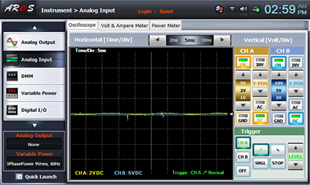
Turn VR3 slowly to the left and measure the waveform and voltage of the gate and both ends of lamp load when the lamp is turned on and when VR3 is turned to the left as much as possible and record the result in the relevant column of table 8-5.


- 3After the measurement, choose variable power at left menu of Touch LCD panel and click to cut off the power supply.