PART7Basic Circuit of Semiconductor
Experiment 7 :Function of Multimeter
Theory
A circuit tester(Multimeter) is the measuring instrument of analog type to measure electric parameter, which is most common. As seen in the name, it is composed of measuring instruments for test such as AC voltmeter, DC voltmeter, and ohmmeter and is combined in one unit. Each part can be functioned by controlling the selector switch.
With certain circuit and scale expansion, the multimeter can measure inductance, capacitance and dB. Using the multimeter, FET, UJT, SCR can be measured.
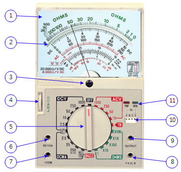
Name of Each Part of Multimeter
① Scale: it is composed of the scale for resistance, voltage, current, dB and the expansion scale. The scale to be measured should be checked out and read.
② Reflection Mirror: it is the part to read the scale, and the needle of the reflection mirror should correspond to the actual needle when reading.
③ This is the part to adjust the scale to be located at 0, which is rarely used but can calibrate the errors occurred by causes such as shock.
④ 0[Ω]ADJ : it is used to make the measuring terminal shorted to become 0[Ω] before measuring the resistance.
⑤ Range Choice Switch: it is the switch to choose AC voltage, DC voltage, Dc current and resistance, and should be turned to the position to be measured. Do not turn this while the measuring terminal is connected.
⑥⑦⑧⑨ Measuring Lead Wire Connector: it is the place to put in the measuring lead wire. Measuring Lead Wire Connector: it is the place to put in the measuring lead wire.
⑥ : it is the connector to measure DC 10A. Red lead wire is used and the range choice switch ⑤ should be located at 250mA of DC mA when measuring. (It varies according to the manufacturer and separate DC 10A location is provided.)
⑦ : it is -COM terminal which is a common terminal for current, voltage, resistance measurement, and black lead wire is used.
⑧ : it is +V, Ω, A terminal, and red lead wire is used, and this measures AC voltage, DC voltage, DC current and resistance.
⑨ : it is OUTPUT terminal used for dB measurement.
⑩ Transistor Check Terminal: it is a socket to check the polarity and quality of transistor. When the range choice switch ⑤ is located at TR, the LED of ⑪(red, green) flickers in turn, and if the polarity of transistor is correct, only one side flickers.
⑪ Red, Green LED: When checking the transistor, if red LED flickers, it is PNP transistor, and if green LED flickers, NPN transistor.
DC Voltage and AC Voltage Measurement
Connect the black lead wire to ‘-COM' terminal⑦, and red lead wire to ‘+V, Ω, A' terminal⑧.
Locate the range choice switch at the position to be measured, DC V or AC V.
Maximum range is DC 1000V, AC 1000V.
DC Current Measurement
Connect the black lead wire to ‘-COM' terminal⑦, and red lead wire to ‘+V, Ω, A' terminal⑧ under 250mA, and red test probe to ‘DC 10A’ terminal⑥ between 250mA and 10A.
Locate the range choice switch at the position to be measured.
When it is over 250mA, the range choice switch must choose ‘DC10A’.
Resistance Measurement
Connect the black lead wire to ‘-COM' terminal⑦, and red lead wire to ‘+V, Ω, A' terminal⑧.
Locate the range choice switch at the position to be measured.
Before measuring the resistance, make the red and black lead wires shorted, and adjust 0[Ω]ADJ④ to become 0[Ω].
Cautions for Using Multimeter
- Follow the safety standard for measuring instrument when measuring high voltage.
- Check out if the needle of the measuring instrument is located at “0” before the measurement.
- Check out if the range choice switch and the lead wire are at proper positions before the measurement.
- you do not know the measuring position well, choose from the highest range.
- After the measurement, turn off the measured object and locate the range choice switch at OFF.
Experiment 7-7.1
1.Circuit Connection
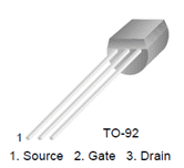
1.FET Measurement: Use Block e of M07 board.
Used FET : KSK30A
Type : Silicon N-channel Junction FET
Symbol: 
3.Measurement
- 1To measure FET, locate the range choice switch of the multimeter at R×1k, and connect red lead wire to S(Source) terminal and black lead wire to G(Gate) terminal of FET.
Record the value indicated at the multimeter in the relevant column of table 7-12.
Measure by changing red lead wire and black lead wire and record the measured value.
- 2Connect the black lead wire to G(Gate) terminal, and red probe to D(Drain) terminal.
Record the value indicated at the multimeter.
Measure by changing red lead wire and black lead wire and record the measured value.
- 3In the measured result of 1) and 2), is FET P channel or N channel?
- 4Connect the black lead wire to D(Drain) terminal, and red probe to S(Source) terminal.
Record the value indicated at the multimeter.
Measure by changing red lead wire and black lead wire and record the measured value.
How are the two relationships?
- 5What change occurs when black lead wire is connected to D terminal, and red lead wire is to S terminal and G part is touched by fingers?
Does the resistance value increase or decrease?
Is this FET usable?
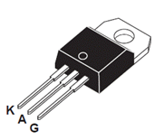
4.SCR Measurement: Use Block d of M07 board.
Used SCR : TYN610
TYN1010 Family of Silicon Controlled Rectifiers
Symbol : 
6.Measurement
- 1To measure SCR, locate the range choice switch of the multimeter at R×1k, and connect red lead wire to K(Cathode) terminal and black lead wire to A(Anode) terminal of SCR.
Record the value indicated at the multimeter in the relevant column of table 7-12.
Measure by changing red lead wire and black lead wire and record the measured value.
- 2Connect the black lead wire to A(Anode) terminal, and red lead wire to G(Gate) terminal.
Record the value indicated at the multimeter.
Measure by changing red lead wire and black lead wire and record the measured value.
- 3Connect the black lead wire to G(Gate) terminal, and red lead wire to K(Cathode) terminal.
Record the value indicated at the multimeter.
Measure by changing red lead wire and black lead wire and record the measured value.
- 4Locate the range choice switch of the multimeter at R×1, and connect red lead wire to K(Cathode) terminal and black lead wire to A(Anode) terminal of SCR.
Record the value indicated at the multimeter.
Using black lead wire, connect to A terminal and G terminal at the same time and record the measured value.
Plug out the black lead wire from G terminal and record the resistance value of A terminal and K terminal indicated by the multimeter.
- 5Is this SCR usable?
7.UJT Measurement: Use Block d of M07 board.
Used UJT : 2N4871
PN unijunction transistor in a TO–92 type
Symbol : 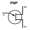
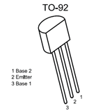
9.Measurement
- 1To measure UJT, locate the range choice switch of the multimeter at R×10, and connect red lead wire to B2(Base2) terminal and black lead wire to B1(Base1) terminal of UJT.
Record the value indicated at the multimeter in the relevant column of table 7-12.
Measure by changing red lead wire and black lead wire and record the measured value.
- 2Connect the black lead wire to E(Emitter) terminal, and red lead wire to B1 terminal.
Record the value indicated at the multimeter.
Measure by changing red lead wire and black lead wire and record the measured value.
- 3Connect the black lead wire to G(Gate) terminal, and red lead wire to K(Cathode) terminal.
Record the value indicated at the multimeter.
Measure by changing red lead wire and black lead wire and record the measured value.
- 4Locate the range choice switch of the multimeter at R×1, and connect red lead wire to K(Cathode) terminal and black lead wire to A(Anode) terminal of SCR.
Record the value indicated at the multimeter.
Using black lead wire, connect to A terminal and G terminal at the same time and record the measured value.
Plug out the black lead wire from G terminal and record the resistance value of A terminal and K terminal indicated by the multimeter.
- 5Is this SCR usable?
Experiment Result Report
1. Experiment Result Table
2. Review and Explanation
1) In table7-12, identify the polarity of each semiconductor and explain the operational state
- FET
- SCR
- UJT


