PART7Basic Circuit of Semiconductor
Experiment 4 :Characteristic of Zener Diode
Theory
Zener diode is the element frequenctly used to get constant voltage or standard power. Unlike normal diode, zener diode uses the reversely applied voltage. The I-V characteristic curve of zener diode is as fig.7-18. When operated within forward bias area, zener diode is same as general rectification diode.
If reverse voltage VR is applied before the setup value as reverse bias to zener diode, very small reverse current IR flows and reaches the setup value. This setup value of the voltage is called the breakdown voltage or zener voltage(Vz). The reverse current rapidly increases at Vz but the voltage is maintained nearly constant.
This is called zener effect and zener diode is the diode whose impurity amount mixed to the semiconductor is adjusted so that this effect can occur with relatively low voltage. There are two reasons that the current flows rapidly when reverse voltage is applied to zener diode. One is zener breakdown by tunnel effect and the other is avalanche breakdown.
Zener diode uses these two effects altogether. At the zener diode with relatively low voltage, zener breakdown is frequently used and at the zener diode with relatively high voltage, avalanche breakdown is. At the zener diode around 5V, two effects are mixed and used in proper rate.
Avalanche Phenomenon
When the carrier among the semiconductor is accelerated in strong electric field, it draws out the valence electron from the orbit with the energy and creates a new carrier. And the new carrier is also accelerated and repeats same operation so the current increases as the avalanche.
The tunnel effect has negative temperature coefficient and the avalanche effect has positive temperature coefficient. Therefore, the temperature characteristic of zener diode is very different according to zener voltage. The tunnerl effect and avalanche effect acts in similar rate around 5V so the temperature coefficients cancels each other out and the change of zener voltage by the temperature change rarely exists
Zener voltage is determined by the design of zener diode and the used material. Actually, the zener current is designed to flow with in the range from IZT to IZN.
The value of IZT depends on the maximum power consumption of the zener diode of PMAX = VZ IZM.
Experiment Process
1. Use Block a of M07 to experiment the characteristic of forward and reverse current of zener diode.
2. Connect the measuring instrument to measure the reverse current and the voltage of zener diode and compose a circuit as in fig.7-19(a).
3. Change the input voltage as in table 7-8 and measure the reverse current (IF) and the voltage between zener diode’s both ends and record the result in the relevant column.
4. Compose a circuit as in fig.7-19(b) for forward characteristic and execute the process above.
tab1Experiment 7-4.1 Measurement of Zener Diode Characteristic
1.Connection(Block a of M07)
1.Circuit Connection
In Block a, connect between the left terminal of R2 and center(middle) terminal with yellow line.
2.Power Connection
Connect between Variable Power V1 terminal of M07 board and upper terminal of VR1 of Block a with red line, and between COM terminal and the earthing terminal with black line.
3.Measuring Instrument Connection
Ammeter Connection
Measure by using the current measurement function of separate digital multimeter.
Measuring the current (IF) flowing to zener diode: Connect the red line of digital multimeter to the right terminal of SW1 of Block a and the black line to the upper terminal of zener diode ZD.
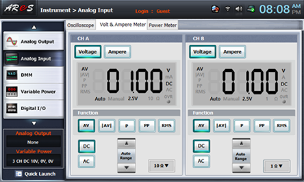
Voltmeter Connection
Measuring input voltage: In Block a, connect between the left terminal of resistance R2 and A+ terminal of Signal Input CH A on front panel with red line, and between the earthing terminal and A- terminal with black line.
Measuring voltage (VD) between zener diode’s both ends: In Block a, connect between the upper terminal of zener diode ZE and B+ terminal of Signal Input CH B on front panel with red line, and between the earthing terminal and B- terminal with black line.
2.Wiring Diagram
flash
3.Measurement
- <Characteristic of Reverse Direction>
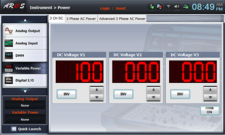
1Click variable power at left menu of Touch LCD panel and choose 3 CH DC tab.At DC Voltage 1, click on the right to become .
Click and apply the output of DC 10V to the input of Block a.
- 2Choose dmm at left menu of Touch LCD panel and click .
- 3Adjust VR1 and change the input voltage as in table 7-8 and record the reverse current value (IR) indicated at the separated digital multimeter, the input voltage(CH A) measured at Voltage& Ampere meter and the voltage between both ends of zener diode(CH B) (VD) in table 7-8.
- 4After the measurement, click to cut off the output.
- <Characteristic of Forward Direction>
5Click variable power at left menu of Touch LCD panel and choose 3 CH DC tab.At DC Voltage 1, click on the right to become .
Click to make -10V.
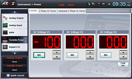
Click to apply the output of DC -10V to the input of Block a.
- 6Change the input voltage as (-VD) in table 7-8 and record the forward current value (IF) indicated at the separated digital multimeter, the input voltage(CH A) measured at Voltage& Ampere meter and the voltage between both ends of zener diode(CH B) (-VD) in table 7-8.
- 7After the measurement, click to cut off the output.
Experiment Result Report
1. Experiment Result Table
2. Review and Explanation
1) In table 7-8, check out the zener voltage and the current flowing when the zener diode is operated.
2) Check out the zener voltage and the flowing current when applying the maximum voltage.
3) Draw the characteristic curve of zener diode using the measured value in table 7-8.