


PART1R, L, C Circuit
Experiment 17 :Characteristic of Transformer
Theory
This is a transformer to change single phase AC voltage, and is composed of a core and high and low voltage coils wound to the core. This is used to supply single phase power and sometimes to supply 3 phase power.
A. Principle of Transformer
Faraday’s Law: The size of induced electromotive force changes according to the number of flux lines that cut the coil and the changing speed.
Lenz’s Law: The direction of induced electromotive force occurs in direction of deterring the electromotive force.
Ampere’s Right-handed Screw Rule: When the current flow through the coil, the magnetic flux occurs in direction of progress of the screw.
B. Induced Electromotive Force
When v1 = √ 2 V1 sin ωt[V] is applied to primary terminal, that is, source side, alternate magnetic flux Φ[ωb] occurs among the core, and at the secondary coil which is interlinkaged to this magnetic flux, the induced electromotive force occurs, which is caused by electromagnetic induction and which is proportional to the number of coil.
- V1 : primary terminal voltage (source side)
- V2: secondary terminal voltage (load side)
- e1 : primary electromotive force (self-induced electromotive force)
- e2 : secondary electromotive force (mutual induced electromotive force)
- n1 : primary coil number
- n2 : secondary coil number
- Φ : alternate magnetic flux
Voltage Ratio(Turn Ratio) :
C. Type of Transformer
- Core type: the coil is arranged concentrically at both core
- Shell type: high/low voltage coils are arranged in turn at inner side of core
- Wound core type: this is made by winding silicon steel strip of cold rolling
D. Rating of Transformer
- Rated capacity: this is the product of rated secondary voltage and rated secondary current under rated frequency. The unit is [VA], [KVA].
- Rated voltage: this is the terminal voltage of secondary coil recorded on the rating plate.
- Rated Current: rated secondary current means the value produced by dividing rated capacity with rated secondary voltage.
Experiment Process
1. In M01 module, connect as in fig.1-28 using Block g.
2. Measure the resistance value of primary and secondary sides of T1 using digital multimeter. The primary side is the left side(4-5), and the secondary side the right side(1-3). Measure the resistance value of upper parts and lower parts with the middle tap of secondary side as center and record the result in the relevant column of table 1-17.
3. Set up the output wave form of function generator as sine wave, the output frequency as 10kHz, and the output voltage as 20Vpp and connect to the primary side, and measure each voltage of the secondary side and record the result in the relevant column of table 1-17.
tab1Experiment 1-17.1 In M01, compose a circuit as in fig.1-28.
1.Connection(M01 Module)
1.Connect the measuring module(ARES-EI-M01) to the platform.
2.Power Connection
In M01 module, connect between A+ terminal of Function Generator and terminal 4 of T1 of Block g with red line, and between A- terminal and terminal 5 of T1 with black line.
3.Measuring Instrument Connection
Voltmeter Connection
V1 Measurement: Connect between A+ terminal of Signal Input CH A on front panel and terminal 1 of T1 of Block g with red line, and between A- terminal and terminal 2 of T1 with black line.
V2 Measurement: Connect between B+ terminal of Signal Input CH B on front panel and terminal 2 of T1 of Block g with red line, and between B- terminal and terminal 3 of T1 with black line.
Vt Measurement: Connect between High terminal of Multimeter on front panel and terminal 1 of T1 of Block g with red line, and between Low terminal and terminal 3 of T1 with black line.
2.Wiring Diagram
flash
3.Measurement
- <Resistance Measurement>
1VR1 Resistance MeasurementConnect between High terminal of multimeter and terminal 4 of Block g with red line, and connect between Low terminal and terminal 5.
When you choose dmm at left menu of Touch LCD panel, Digital Multimeter window appears, and if you click , the resistance value is indicated.
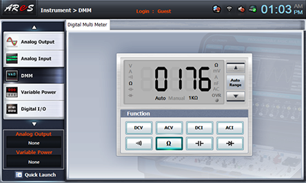
Measure the resistance value between terminal 1-3, 1-2, 2-3 and record the result in table 1-17.
After the measurement, make a connection as in [Experiment Process].
- <Voltage Measurement>
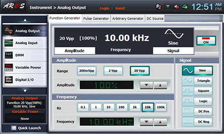
1Choose analog output at left menu of front panel.In Function Generator window, set up Amplitude as , Frequency as , Signal as and click to output 10KHz 20Vp-p.
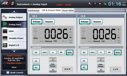
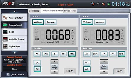
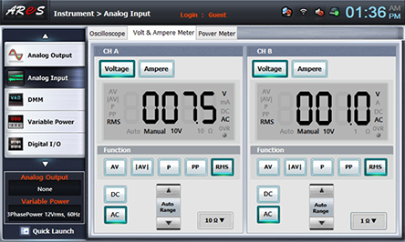
- 2Click analog input at left menu of Touch LCD panel, then Oscilloscope window appears, then choose Volt & Ampere Meter tab and click , , at CH A, and then the voltage value is indicated.
Here, CH A is V1, and CH B is V2 value, so record this value in the relevant column of table 1-17.
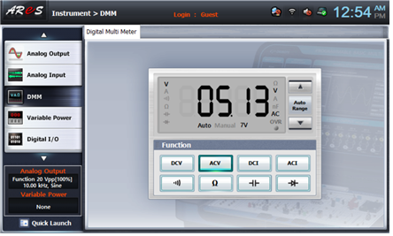
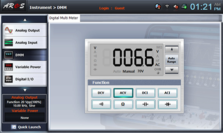
- 3If you click dmm at left menu of Touch LCD panel and click , Vt voltage value is indicated. Record the result in the relevant column of table 1-17.
- 4Input Voltage Measurement
Connect between High terminal of multimeter on front panel and terminal 1 of T1 of Block g with red line, and connect between Low terminal and terminal 3 of T1 with black line.
If you click dmm at left menu of Touch LCD panel and click , Vt voltage value is indicated. Record the result in the relevant column of table 1-17.
- 5Apply the input to the secondary side and measure the output at the primary side
In M01 module, connect between A+ terminal of Function Generator and terminal 1 of T1 of Block g with red line, and between A- terminal and terminal 3 of T1 with black line.
<Voltmeter Connection>
Input Voltage Measurement: Connect between A+ terminal of Signal Input CH A on front panel and terminal 1 of T1 of Block g with red line, and between A- terminal and terminal 3 of T1 with black line.
Output Voltage Measurement: Connect between B+ terminal of Signal Input CH B on front panel and terminal 4 of T1 of Block g with red line, and between B- terminal and terminal 5 of T1 with black line.
Click analog input at left menu of Touch LCD panel, then Oscilloscope window appears, then choose Volt & Ampere Meter tab and click , , at CH A, and then the voltage value is indicated.
Here, CH A is the input voltage and CH B the output voltage. Record this value in the relevant column of table 1-17.
Wiring Diagram
flash
- 6After the measurement, click at Analog Output to cut off the output.
Experiment Process

1. In M01 module, connect as in fig.1-29 using Block g.
2. Supply 12V 60Hz as the output voltage of power supply, measure the voltage applied to R10 and R11 using digital multimeter and AC voltmeter and record the result in the relevant column of table 1-17.
tab2Experiment 1-17.2 In M01, compose a circuit as in fig.1-29.
1.Connection(M01 Module)
1.Connect the measuring module(ARES-EI-M01) to the platform.
2.Circuit Connection
Connect between right terminal of T1 and upper terminal of R11 with yellow line. 3) Power Connection
In M01 module, connect between V1 terminal of Variable Power on the left and left terminal of R10 of Block g with red line, and between COM terminal and SW2 left terminal with black line.
3.Measuring Instrument Connection
Vi Measurement: Connect between A+ terminal of Signal Input CH A on front panel and right terminal of R10 of Block g with red line, and between A- terminal and terminal 4 of T1 with black line.
Vo Measurement: Connect between B+ terminal of Signal Input CH B on front panel and upper terminal of R11 of Block g with red line, and between B- terminal and terminal 3 of T1 with black line.
2.Wiring Diagram
flash
3.Measurement
- 1Choose variable power at left menu of Touch LCD panel.
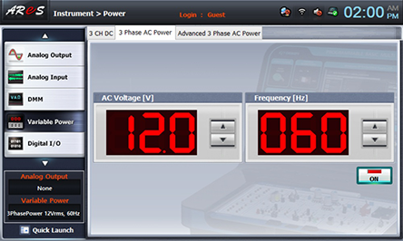
- 2Choose 3 CH DC tab and click at AC Voltage to set up 12V.
Double click AC Voltage V1 and use Quick Number Keypad, and the number is set up directly.
Click , then it is as the fig. below, and the output of AC 12V is inputted to the circuit.
- 3Click analog input at left menu of Touch LCD panel, then Oscilloscope window appears, then choose Volt & Ampere Meter tab and click , , at CH A, and then the voltage value is indicated.
Here, CH A is Vi, the voltage between R10’s both ends, and CH B is Vo, the voltage between R11’s both ends. Record this value in the relevant column of table 1-17.
Remove the yellow line connected between right terminal of T1 and upper terminal of R11 and measure and record the voltage applied to R10.
- 4After the measurement, click at Analog Output to cut off the output.
Experiment Result Report
1. Experiment Result Table
2. Review and Explanation
1) In the result (A) of table 3-17, calculate the voltage ratio of input to output.
Voltage Ratio(Turn Ratio) :