


PART5Fleming’s Law
Experiment Purpose
- 1.Understand electric motor and generator.
- 2.Understand Fleming’s law.
Experiment 1 :Fleming’s Law
Theory
Fleming’s Right Hand Rule
When the conducting line moves within the magnetic field, the electric charge within the conducting line moves by the Lorentz force so the current flows within the line. This can be interpreted that the induced electromotive force is generated to the conducting line. By using Fleming’s right hand rule, the direction of induced electromotive force or induced current can be determined if the direction of magnetic field and that of the conducting line movement are known.
If the right thumb is the moving direction of the conducting line, and if the index finger is the direction of magnetic field, then the direction of middle finger is the direction of induced electromotive force or induced current.
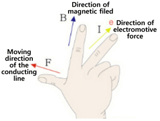
Principle of Generator
According to Fleming’s right hand rule, the kinetic energy of the conducting line can be converted as electric energy within the magnetic field. This is the basic principle of the generator. The waterpower generation, thermal power generation, nuclear power generation are different in type but are same in that they change the original energy to the kinetic energy by turbine and change it again to the electric energy.
Fleming’s Left Hand Rule
When the current flows through the conducting line within the magnetic field, the line gets the force by Lorentz force applied to the electric charge. By using Fleming’s left hand rule, the direction of force which the conducting line gets can be determined if the direction of magnetic field and that of the current flow are known. If the left index finger is the direction of magnetic field, and if the middle finger is the direction of the current, then the direction of the thumb is the direction of force which the conducting line gets.
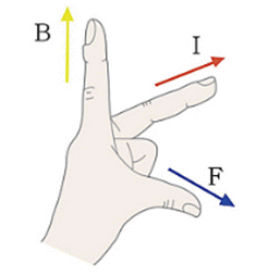
Principle of Electric Motor
According to Fleming’s left hand rule, the electric energy within the conducting line can be converted to kinetic energy within the magnetic field. This is the principle of the electric motor that executes rotary motion using the electric energy. The electric motor exists behind the wing of the fan and the motor can be seen as the energy converter that converts the electric energy to the kinetic energy.
Experiment Process
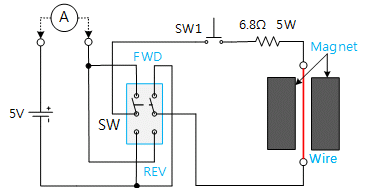
1. In Block a of M05 board, make a connection as in fig.5-4 and locate SW at FWD.
2. Apply DC 5V to the circuit, describe the direction of the wire when SW1 is pressed, and record the measured value of ammeter in the relevant column of table 5-1.
(The pressed time should not be too long.)
- Describe the direction of flowing current based on the direction of the compass.
3. Describe the direction of the wire when SW is reversed(REV) and record the measured value of ammeter in the relevant column of table 5-1.
4. Based on the experiment above, describe how Fleming’s law is applied.
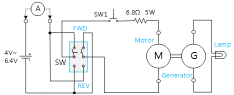
5. In Block b of M05 board, make a connection as in fig.5-4. Then how is the brightness of the lamp changed when the voltage is increased from 4V to 6.4V?
- Explain the principles of the motor and the generator.
Experiment 5-1.1
1.Connection
1.Power Source and Measuring Instrument Connection
Connect between Fixed Power 5V terminal on the left of M05 board and mA/A terminal of multimeter on front panel with red line, and between Low terminal and V+ terminal of Block a with red line.
Connect between Fixed Power GND terminal on the left of M05 board and the earthing terminal with black line.
2.Wiring Diagram
flash
3.Measurement
- 1Click dmm at left menu of Touch LCD panel, then Digital Multimeter window appears, and if you click here, the current value is indicated.
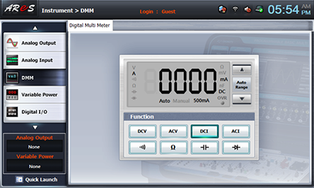
- 2Click SW1 and measure the current value indicated at DMM, and record the direction of wire in the relevant column of table 5-1.
Measure the current value when SW is reversed(REV) and record the direction of wire in the relevant column of table 5-1.
- 3In Block b of M05 board, make a connection as in fig.5-4.
Wiring Diagram
flash
Choose quick launch at bottom of left menu on front panel and click Variable Power .

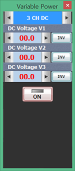
- 4Choose 3 CH DC tab and click at DC Voltage V1 and increase the voltage to become 4V.
If you click , the DC output is applied to the circuit.
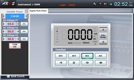
Measure the current value indicated at DMM and the brightness of the lamp and and record the result in the relevant column of table 5-1.
Check out the value of current and the brightness of the lamp by increasing the voltage to 6.4V and record the result in the relevant column of table 5-1.
Experiment Result Report
1. Experiment Result Table
2. Review and Explanation
1) In table 5-1 Block a experiment, describe how Fleming’s law is applied.
In Block b experiment, experiment the principle of motor and generator.