PART2Electric Magnetic Circuit
Experiment 2 :Magnet Field
Theory
Magnetic Field
Magnetic field affects not only the other magnetic needle put within the field but also the current passing through the field, and if the conductor is moved within the magnetic field, the electromotive force is induced within the conductor.
That is, it is a space to which special characteristics are given by stimulus or current. The interaction between the current and magnetic field shows the close relationship between electric phenomenon and magnetic phenomenon, and is used with many electric devices such as motor or generator.
The characteristic of magnetic field is the intensity of magnetic force that each point within the magnetic field possesses potentially. This is called the intensity of magnetic field(in short, magnetic field), and the intensity of magnetic field at one point means the size and direction of magnetic force when positive magnetic charge is put at the point within the magnetic field.
When the unit of magnetic charge is used as CGS electromagnetism unit, oerdsted is used as the unit of magnetic field(sign Oe). That is, when 1dyne of force reaches the positive magnetic charge of 1CGS, the intensity of magnetic field at the point is 1Oe. Beside this, ampere turn/meter(AT/m) is also used which is determined by the magnetic action of current.
Experiment Process
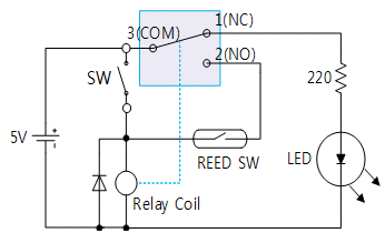
1. In M02 board, make a connection as in fig.2-18 using Block a.
2. Connect the power of DC power supply as 5V.
3. Check out the lighting of LED and operation of relay when SW is on and record the result in the relevant column of table 2-2.
4. Check out the lighting of LED and operation of relay when SW is off and record the result in the relevant column of table 2-2.
5. Connect between contact 3 and 4 and check out the lighting of LED and operation of relay when the magnet gets near to REED SW and record the result in the relevant column of table 2-2.
6. Describe the way to be used as in process 5.
tab1Experiment 2-2.1
1.Connection
1.Power Connection
Connect between Fixed Power +5V terminal on the left of M02 board and V+ terminal of Block a with red line.
The earthing(-) is internally connected.
2.Wiring Diagram
3.Measurement
- 1Check out the lighting of LED and operation of relay when connecting as in the wiring diagram and record the result in the relevant column of table 2-2.
- 2Connect between the left terminal of relay contact 3 and upper terminal of relay coil with yellow line, and check out the lighting of LED and operation of relay and record the result in the relevant column of table 2-2.
- 3Connect between the left terminal of relay contact 3 and right terminal of relay contact 2 with yellow line, and check out the lighting of LED and operation of relay and record the result in the relevant column of table 2-2.
- 4Connect between the left terminal of relay contact 3 and right terminal of relay contact 2 with yellow line, and check out the lighting of LED and operation of relay when the magnet gets near to reed SW and record the result in the relevant column of table 2-2.


