PART3Electromagnetic Field Circuit
Experiment 2 :Intensity of Magnetic Field
Theory
When you put a compass around a magnet, the magnetic needle of the compass gets the force and moves. Like this, the area where the force of magnet reaches is called magnetic field, and since this is invisible, its direction and intensity are usually measured by using the compass. The direction of magnetic field is determined as the direction to which the N pole of compass’s magnetic needle points, and the intensity can be guessed by the moving degree of magnetic needle.
The intensity of magnetic field also can be known by scattering iron dust. The denser the iron dust is gathered, the more intense the magnetic field is. In case of a bar magnet, the magnetic field is intense as the intensity of magnet is bigger, or the distance form the magnetic pole is nearer. The magnetic field is also formed when the current flows through the conductor, and in case of straight conductor, the magnetic field is intense as the intensity of current flowing through the conductor is bigger and as it is nearer to the conductor. In case of coil, you can see with the scattered iron dust that its magnetic field is similar to that of a bar magnet. The magnetic field gets more intense as the current flowing through the coil is more intense and as the wound number of the coil is bigger, and the place where the magnetic field is most intense is inside the coil.

Solenoid
In 1819, when Hans Christian Oersted knew that the wire where the current flowed affected the compass, he found out that and the current generated the magnetic field.
If the toroidal coil is wound in the same direction as the coil, many magnetic fields will make the magnetic flux line with denser coil. The magnetic field gets more intense through the coil and that of toroidal coil becomes more intense.
Solenoid is a coil wound in a spiral which is made to generate very intense magnetic field. The magnetic flux line of solenoid is operated in the same way as the magnet.
The magnetic flux moves to S pole leaving N pole behind.
When a metal bar(plunger) is installed at the solenoid, draw the bar within the solenoid and coil drawn in fig.3-6.
The magnetomotive force(mmf) is the magnetizing force generated by the current flowing through the wire. This magnetomotive force is dependent upon the coil’s number of turns and the current flowing through the coil.
Experiment Process
1. In Block c of M03 board, make a connection as in fig.3-6 and locate SW at FWD.
2. Record the measured value when applying DC 12V to the circuit in the relevant column of table 3-2
3. Increase the DC voltage from 5V to 12V, measure the voltage and current when the solenoid is operating(when the plunger is pulled within the coil) and record the result in the relevant column of table 3-2, and record the direction to which the compass points.
4. Measure the voltage and current when SW is reversed(REV) and record the result in the relevant column of table 3-2, and record the direction to which the compass points.
tab1Experiment 3-2.1
1.Connection
1.Power Connection
Connect between Variable Power V1 terminal on the left of M03 board and V+ terminal of Block c with red line, and between COM terminal and earthing terminal with black line.
2.Measuring Instrument Connection
In the multimeter on front panel, connect between mA/A terminal and left terminal of ammeter of Block c with red line, and between Low terminal and the right terminal of ammeter with black line.
2.Wiring Diagram
flash
3.Measurement
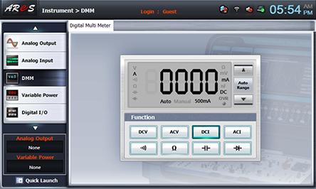
- 1Click dmm at left menu of Touch LCD panel, then Digital Multimeter window appears, and if you click here, the current value is indicated.
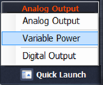
- 2Choose quick launch at bottom of left menu on front panel and click Variable Power .
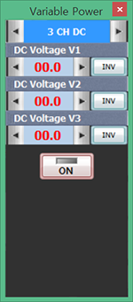
- 3Choose 3 CH DC tab and click at DC Voltage V1 and increase the voltage to become 12V.
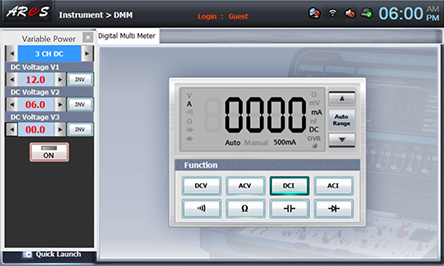
If you click , the DC output is applied to the circuit.
Measure the current value indicated at DMM and the direction to which the compass points and record the result in the relevant column of table 3-2.
Measure the current value and the direction to which the compass points when SW is converted and record the result.
Set up the voltage as 8V, change it as the voltage value in table 3-2 and record the voltage and the current.
Indicate the voltage and current with which the solenoid is operated.
- 4After the measurement, click to cut off the voltage applied to the circuit.
3-2-5 Lentz and Faraday’s Law
Experiment Purpose
- Check out Lentz’s law with the electromagnetic coil.
- Check out Faraday’s law with the electromagnetic coil.
Related Theory
Faraday's Law of Electromagnetic Induction
This law was found by Michael Faraday, an English physicist, in 1831.
Electromagnetic induction means the phenomenon that phase difference(voltage) occurs at the conductor which is located in the place where the magnetic field changes, and the generated voltage is proportional to the change rate of magnetic flux.
As in fig.(a), if the magnet gets near to the coil, the current is induced to the coil. If the magnet gets far from the coil, the current flows in reverse direction. As in fig.(b), if the coil within the magnetic field is pulled, the current flows to the coil as in the fig..
On the contrary, if it is pushed, the current flows in reverse direction. When any power such as battery is not connected to the coil, the movement of magnet or coil should be involved in order for the induced current to flow. However, the induced current does not occur when the magnet stays still even though it is a very strong one.
Like this, electromagnetic induction is the phenomenon that the electromotive force occurs to the conductor according to the change of magnetic field, and this electromotive force is called induced electromotive force, and the current the induced current. In terms of the size of induced electromotive force, Michael Faraday found out that ‘the electromotive force is proportional to the speed that the line of magnetic force penetrating the coil changes’ and this law is called Faraday’s law of electromagnetic induction.
In this formula, ℇ is the induced electromotive force. If the resistance R is connected to the circuit in the fig. above, the current as big as i= ℇ/R flows through the circuit. ΦB on the right side of the formula above is the flux of magnetic field that passes the side surrounded by the circuit. That is, a closed circuit, which is connected by the conductor through which the electricity can flow, is put within the magnetic field, and the change rate of this flux of this magnetic field is same as the induced electromotive force induced to the circuit.
Lentz’s Law
This law was discovered by the German physicist Heinrich Lents, in1834.
In a closed circuit, the induced current(induced electromotive force) occurs in the direction e that disturbs the change of original magnetic flux, or that of the movement of magnet.
In the fig.(a) above, the line of magnetic force (B) occurs in the direction that disturbs the increase of line of magnetic force (B) and the electromotive force is induced(Faraday’s law), and the induced current flows in the direction that follows Ampere’s right-handed screw rule. The induced current flows as in the fig. above according to the wound form of the coil, since the generated line of magnetic force is upward.(When the N pole of the magnet approaches, N pole is induced to the coil.)
In the below fig. of fig(a), the line of magnetic force occurs downward. This is, the direction that disturbs the decrease of line of magnetic force, and in other words, the direction that increases the line of magnetic force, and the electromotive force is induced(Faraday’s law). The induced current flows by the induced electromotive force. (When the N pole of the magnet grows apart, S pole is induced to the coil.)
Experiment Process
1. As in fig.3-9, connect the ammeter using separate galvanometer.
2. Insert and exact the bar magnet inside the coil. What change occurs to the ammeter?
3. Repeat the experiment above by reversing the direction of bar magnet. What is the difference between the previous and the latter?
4. How does the current value change when the magnet stays inside the coil?
printExperiment Result Table
1. Experiment Result Table
<Table 3-1> Draw the magnetic field around the bar magnet below.