


PART1R, L, C Circuit
Experiment 11 :AC Voltage Measurement
Theory
The voltage is the difference of electric potential energy(electric potential). When a stone is thrown into the air, it always falls onto ground. This is the movement of potential energy from higher to lower place, and if the potential energy is same, the stone will not fall. In the electric circuit, if there is no potential difference, the current does not flow. It is like the water does not flow through the pipe with no water pressure. Just as a lot of water flows through the same pipe if water pressure is high, a lot of current flows in the electric circuit if the potential difference(voltage) is big. To measure the potential difference between two points, voltmeter is used by connecting both ends of the load(measurement target). That is, it should be connected in parallel to the load. The voltmeter is the measuring instrument that shows the potential difference between two connected points.
Experiment Process
1. In M01 module, connect as in fig.1-19 using Block a.
2. Adjust the resistance of VR1 to become 1kΩ.
3. Connect the output voltage of power supply as AC 12V, measure the voltage between both ends of R1 and VR1 and record the result in the relevant column of table 1-11.
tab1Experiment 1-11.1 In M01, compose a circuit as in fig.1-19.
1.Connection
1.Connect the measuring module(ARES-EI-M01) to the platform.
2.Circuit Connection
Connect 1, 2 terminals of VR1 on the left of Block a with yellow line.
Connect terminal 1 of VR1 on the left of Block a to the left terminal of VR1 of Block d with yellow line, and terminal 3 to the right terminal with yellow line.
Connect between right terminal of R1 and right terminal of VR1 with yellow line.
3.Power Connection
In M01 module, connect between V1 terminal of Variable Power and left terminal of R1 with red line, and between COM terminal and left terminal of VR1 with black line.
4.Measuring Instrument Connection
Connect between A+ terminal of Signal Input CH A and left terminal of R1 with red line, and between A- terminal and right terminal of R1 with black line.
Connect between B+ terminal of Signal Input CH B and right terminal of VR1 with red line, and between B- terminal and left terminal of VR1 with black line.
2.Wiring Diagram
flash
3.Measurement
- 1How to Set up Resistance of VR1.
To measure the resistance, the power should be cut off from the circuit.
Therefore, remove the yellow line connected between 5k VR1 terminal and left terminal of VR1 of Block a.
Connect between High terminal of multimeter and left terminal of VR1 of Block a with red line, and connect between Low terminal and right terminal of VR1.
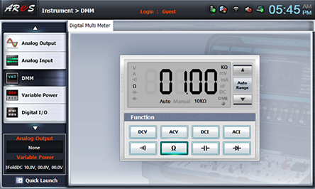
When you choose dmm at left menu of Touch LCD panel, Digital Multimeter window appears, and if you click , the resistance value is indicated. Turn the handle to make 1kΩ.
Remove the line connected to Multimeter, and connect between 5k VR1 and left terminal of VR1 of Block a with yellow line again.
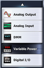
- 2Choose variable power at left menu of Touch LCD panel.
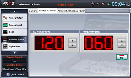
- 3Choose 3 Phase DC tab and click at AC Voltage to set up 12V.
Double click AC Voltage, and use Quick Number Keypad, then the number can be entered directly.
- 4Click analog input , then it is as the fig. below, and the output of AC 12V is inputted to the circuit.
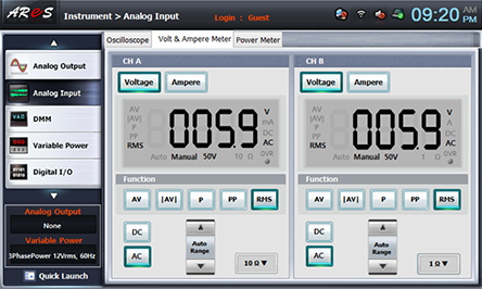
- 5Click analog input at left menu of Touch LCD panel, then Oscilloscope window appears, then choose Volt & Ampere Meter tab and click , , for CH A, CH B, and then the voltage value is indicated.
CH A is the voltage between both ends of R1, and CH B is that of VR1. Record this value in the relevant column of table 1-11.
- 6Change the resistance of VR1 as 200Ω using 1) How to Set up Resistance of VR1, repeat the measuring process above, and record the result in the graph and in the relevant column of table 1-11.
- 7After the measurement, click at Variable Power to cut off the power.