


PART1R, L, C Circuit
Experiment 8 :Superposition, Thevenin-Norton’s Theorem
Theory
Principle of Superposition
When multiple powers are applied at the same time, the reaction(voltage, current) is same as the algebraic sum of the reaction when one power at a time is applied, that is, when only one power is applied while others are 0.
Thevenin’s Theorem
In a linear electric circuit, Thevenin’s theorem explains the electric equivalence by changing any combination of power source, current source and resistance having two terminal into one power source V and one serial resistance R. In AC system, Thevenin’s theorem can be applied not just as a resistance but as general impedance.
- Separate the circuit part where Thevenin’s equivalent circuit will be calculated from the resistance.
- Make all voltage sources be shorted, and open all current sources to calculate Thevenin’s equivalent circuit.
- In the first step, calculate Thevenin’s equivalent voltage that is applied to the separated part of the circuit. Here, all powers should be located at their original position.
- Draw Thevenin’s equivalent circuit. Connect the resistance separated in the first step to the terminal of Thevenin’s equivalent circuit. Now the current flowing through this resistance can be calculated using Ohm’s law.
- To know the voltage or current at RL element in fig.1-12(a), it can be calculated simply by express the rest parts as serial connection of VTH and RTH. In the end, it is important to know how to calculate VTH and RTH. VTH is the state that the load resistance is removed, that is, the terminal voltage of AB in the open circuit. If the voltmeter is connected here, VTH can be measured, and RTH can be calculated by the resistance value when the voltage source within the circuit is shorted and RL is open.
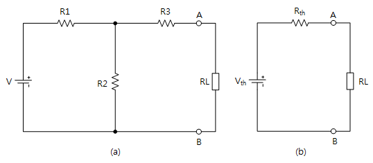
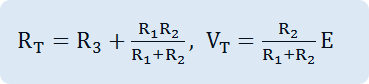
Thevenin’s equivalent circuit can be calculated as in fig.1-12(b) and the formula to calculate Thevenin’s equivalent voltage and equivalent resistance is as below.
Norton’s Theorum
In a electric circuit, any combination of voltage source, current source, and resistance that have two terminals can be converted to ideal current source and parallel resistance to explain electric equivalence.
Norton’s equivalent circuit is used to reanalyze the network of linear power and impedance according to given frequency. The circuit is composed of ideal current source and ideal impedance that is connected in parallel.
Experiment Process
1. Connect M01 module to platform.
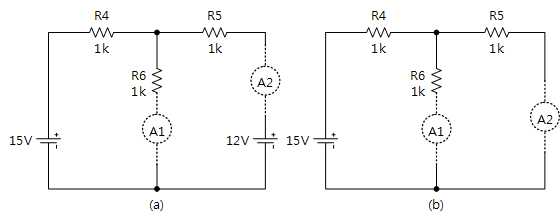
2. Connect as in fig.1-13(a), connect 15V and 12V, and measure the current flowing to R6 and record the result in the relevant column of table 1-8.
3. Change the connection as in fig.1-13(b), measure the current flowing to R6, R5 and record the result in the relevant column of table 1-8.
4. Remove the ammeter of R6 to open the circuit, measure the voltage with DC voltmeter and record the result in the relevant column of table 1-8. This voltage is Thevenin’s equivalent voltage.
5. Connect R5, R6 in parallel and measure parallel combined resistance. This resistance value is Thevenin’s equivalent resistance. (Here, measure after removing 15V power connection.)
6. Calculate Thevenin’s equivalent voltage and equivalent resistance and record the result in the relevant column.
tab1Experiment 1-8.1 In Block c of M01, compose a circuit as in fig.1-13.
1.Connection(Block c of M01)
1.Circuit Connection
Connect between the right terminal of R4 and upper terminal of R6, and between upper terminal of R6 and left terminal of R5 with yellow lines.
2.Power Connection
Connect between V1 terminal of Variable Power on the left of M01 board and R4’s left terminal of Block c with red line.
Connect between V2 terminal of Variable Power on the left of M01 board and R5’s right terminal of Block c with red line.
Connect between COM terminal of Variable Power on the left of M01 board and lower terminal of Block c with black line.
3.Measuring Instrument(Ammeter) Connection
Connect between R6’s lower terminal of Block c and mA/A terminal of Multimeter on front panel with red line, and between lower terminal of Block c and Low terminal with black line.
2.Wiring Diagram
flash
3.Measurement
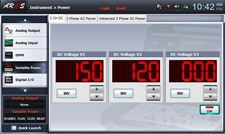
- 1Choose variable power at left menu of Touch LCD panel.

- 2Choose 3 CH DC tab, click at DC Voltage V1 to set up 15V and click at DC Voltage V2 to set up 12V.
Click , and then the output of DC 10V from V1 and that of DC 12V from V2 are inputted to the circuit.
- 3Current of A1 Flowing to R6
Connect as 1. Connection>Ammeter Connection> and click dmm at left menu, then Digital Multimeter window appears, and if you click here, the current value of A1 flowing to R6 appears. Record this in the relevant column of table 1-8.
As in fig.1-13(b), remove the connection between V2 terminal of Variable Power on the left of M01 board and R5’s right terminal of Block c with red line.
Connect between R5’s right terminal and lower terminal with yellow line, measure the current value of A1 flowing to R6 and record the result in the relevant column of table 1-8.
Wiring Diagram
flash
- 4Current of A2 Flowing to R5
Remove the connection between R5’s right terminal and lower terminal with yellow line.
Remove the connection line of multimeter to lower terminal of R6 and that of Block c and connect between them with yellow line.
Connect between R5’s right terminal and mA/A terminal of Multimeter on front panel with red line, and between lower terminal of Block c and Low terminal with black line, measure the current value of A2 flowing to R5 and record the result in the relevant column of table 1-8.
Wiring Diagram
flash
- 5Thevenin’s Equivalent Voltage Measurement
Remove the yellow lines connected to lower terminal of R6 and to that of Block c, connect between A+ terminal of Signal Input CH A on front panel and lower terminal of R6 with red line, and between A- terminal and lower terminal with black line.
Wiring Diagram
flash
Resistance Measurement
1. Measurement
- 1In M01, remove the red line connected to V1 terminal of Variable Power.
Connect between the right terminal of R4 and upper terminal of R6, between lower terminal of R6 and lower terminal of Block c, and between the right terminal of R5 and lower terminal of Block c with yellow lines.
- 2Choose dmm at left menu of Touch LCD panel and click at Digital Multimeter window.
- 3Connect between High terminal of Multimeter on front panel and left terminal of R4 of Block b with red line, and between Low terminal and lower terminal with black line, and record the measured value in the window in table 1-8.
Wiring Diagram
flash