


PART1R, L, C Circuit
Experiment 5 :Ohm’s Law
Theory
Ohm’s law defines the interrelationship between voltage(V), current(I) and resistance(R). That is, the voltage is proportional to the current and the resistance, and the current and the resistance are inversely proportional to each other Voltage means the potential difference between two points, meaning electro(current)-pressure, and the sign is “V” and the unit is V(Volt).
The current means the movement of electric charge, and the direction that it moves is determined as + direction. When the current flowing within unit time(sec) is expressed, it is indicated as “I” in sign, and in unit, it is expressed as A(Ampere). The resistance, expressed as "R", means the degree to which the flow of current is disturbed, and its unit is Ω(ohm). When the current of 1A flows under the voltage of 1V, the resistance of this circuit is 1Ω. If Ohm’s law is expressed as formula, it is as below.
Experiment Process
1. Connect R1 of Block a as in fig.1-6, and measure the current flowing through the circuit and record the result in table 1-4.
2. Measure the current flowing through R9 of Block f, and that flowing through R16 of Block k and record the result in the relevant columns
3. Calculate the current for each resistance by the formula and compare it to the measured value.
tab1Experiment 1-5.1 In M01, compose a circuit as in fig.1-6.
1.Connection(M01 Module)
1.Connect the measuring module(ARES-EI-M01) to the platform
2.Power and Measuring Instrument Connection
Connect between V1 terminal of Variable Power and mA/A terminal of multimeter on front panel with red line, and between Low terminal and the left terminal of R1 of Block a with red line.
Connect between COM terminal of multimeter and the right terminal of R1 with black line.
2.Wiring Diagram
flash
3.Measurement
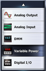
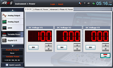
- 1Choose variable power at left menu of Touch LCD panel.
- 2Choose 3 CH DC tab and click at DC Voltage V1 to set up 10V.3
- 3Click , and then the output of DC 10V is inputted to the circuit.
- 4Click dmm at left menu, then Digital Multi Meter window appears. If you click here, the current value is displayed.
- 5How to Measure the Current Flowing through R9
Connect between V1 terminal of Variable Power and mA/A terminal of multimeter on front panel with red line, and between Low terminal and the left terminal of R9 of Block f with red line.
Connect between COM terminal of Variable Power and the right terminal of R9 of Block f with black line.
Record the measured value of current of Digital Multimeter window in the relevant column of table 1-4.
Wiring Diagram
flash
- 6How to Measure the Current Flowing through R16
Connect between V1 terminal of Variable Power and mA/A terminal of multimeter on front panel with red line, and between Low terminal and the left terminal of R16 of Block k with red line.
Connect between COM terminal of Variable Power and the right terminal of R16 of Block k with black line.
Record the measured value of current of Digital Multimeter window in the relevant column of table 1-4.
Wiring Diagram
flash