


PART8Basic Electrical Circuit
Experiment 7 :Touch Control Switch
Theory
This is the circuit that detects the touch by the electromotive force of human body. When the hand touches the input part of touch sensor, the surface electromotive force is detected by the charging/discharging of the condenser.
Capacitive touch sensor operates by detecting the change of capacitance when human body or certain object is touched. It indicates the final output as High or Low by detecting the difference between small change of capacitance when the human body touches the plate and the setup value. Generally, the case is made of insulated material and conductive material cannot be used. (Capacitance, generated by direct contact to the surface or indirect contact through insulator case, is proportional to the area and inversely proportional to the distance.)
The touching part of touch sensor is made of metal. If small amount of current flows through the metal, it becomes operation standby state. If the user touches the switch, the electricity flows to human body and the voltage changes in short time and the internal circuit reacts to the voltage and the output changes. That is, it operates with the human body becoming a battery. If the user touches the switch with holding conductive metal such as chopstick or spoon, the output changes. However, if he/she touches the switch with insulator, the output does not change.
Fig.8-27 is the touch control switch applying the characteristic of high-input impedance FET. When the touch plate is not touched, FET is saturated and bias voltage is not applied to the base of TR7 so the transistor TR7 is cutoff. The collector of TR7 becomes high potential and it cuts off TR8 and LED is turned off. In short, if the touch plate is not touched, it means the switch is off.
If human body touches the touch plate, the signal conducted by human body operates FET as cutoff state, so FET drain polarity becomes high potential and it operates TR7. Therefore, the collector of TR7 becomes low potential and it operates TR8 and the current flows from the emitter to the collector so LED is turned on. This means the switch is on.
Experiment Process
1. Using Block g of M08, make a connection as in fig.8-27.
2. Connect the power of power supply as DC 10V.
- Turn on the SW7.
3. Measure below when the touch plate is not touched and record the result in the relevant column of table 8-12.
- lighting of LED
4. Measure below when the touch plate is touched and record the result in the relevant column of table 8-12.
- lighting of LED
5. Measure the voltage of test point using DC voltmeter and record the result in the relevant column of table 8-12.
tab1Experiment 8-7.1
1.Connection(Block g of M08)
1.Circuit Connection
In Block g of M08 board, connect between the lower terminal of TR8 and upper terminal of R25 with yellow line.
2.Power Connection
Connect between V1 termiinal of Variable Power on the left of M08 board and V+ terminal of Block g with red line, and between COM terminal and the earthing terminal with black line.
3.Measuring Instrument Connection
Voltmeter Connection
Connect between High terminal of Multimeter on front panel and the base terminal of TR7 of Block g on M08 board with red line, and between Low terminal and the earthing terminal of Block g with black line.
2.Wiring Diagram
flash
3.Measurement
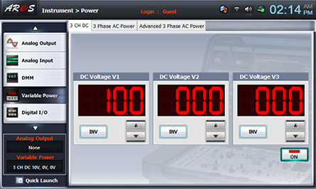
- 1Choose variable power at left menu of Touch LCD panel and set up at 3 CH DC for DC Voltage V1 to become 10V.
Click , and supply the output of DC 10V to the circuit, and turn on the SW7.
- 2Measure below when the touch plate is not touched and record the result in the relevant column of table 8-12.
lighting of LED
- 3Choose dmm at left menu of Touch LCD panel and click .
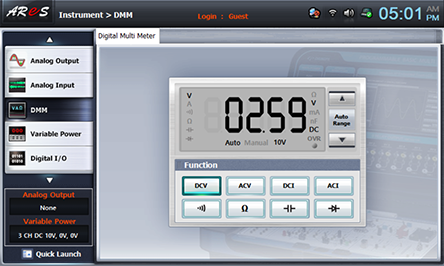
Record the measured value(VB) in the relevant column of table 8-12.
Disconnect the red lead wire connecting between High terminal of Multimeter on front panel and the base terminal of TR7 of Block g on M08 board. Connect it again to the collector(VC) of TR7, base(VE) of TR8, emitter(VF) of TR8 and measure and record the voltage in the relevant column of table 8-12.
- 4Measure below when the touch plate is touched and record the result in the relevant column of table 8-12.
lighting of LED
Execute process 3) above and record the result.
- 5After the measurement, choose variable power at left menu of Touch LCD panel, click to cut off the power supply.