


PART10Characteristic Circuit of Electric Element
Experiment 5 :Sound Control Circuit
Theory
A basic sound control switch circuit is expressed in fig.10-5 below. Two cascade joint amplification circuits are composed of TR3 and TR4. The signal is amplified from the mic, and AC signal is output as rectification and filtering circuit. The mic at the circuit is an element that changes the audio signal to electric signal. The rectification and filter circuit is composed of D5 and C5, and is converted as the output signal through TR4. Here, TR5 and LED2 are turned on and DC voltage has positive value. The negative signal flows to the earthing through D4.
If the audio signal is converted to electric signal by the mic, it is combined as cascade joint input and the signal is amplified, and also it is combined to the rectifier through C3. If the DC voltage applied to C5 reaches 0.7V, LED is turned on through TR5.
Experiment Process
1. Using Block c of M10 board, make a connection as in fig.10-5.
2. Make the output power of DC power supplier as 10V and connect it to the circuit.
- Check out if LED2 is turned on.
3. Measure each measuring point with DC voltmeter and record the result in table 10-5.
4. Approach your mouth to the mic and make a sound. Measure the voltage of each measuring point if LED is turned on and record in table 10-5.
5. Can you determine if this sound control circuit operates normally?
tab1Experiment 10-5.1
1.Connection(Block c of M10)
1.Power Connection
Connect between V1 terminal of Variable Power on the left of M10 board and the V+ terminal of Block c with red line, and between COM terminal and the earthing terminal with black line
2.Measuring Instrument Connection
Connect between High terminal of Multimeter on front panel and the base terminal of TR3 of Block C on M10 board with red line, and between Low terminal and the earthing terminal of Block c with black line.
2.Wiring Diagram
flash
3.Measurement
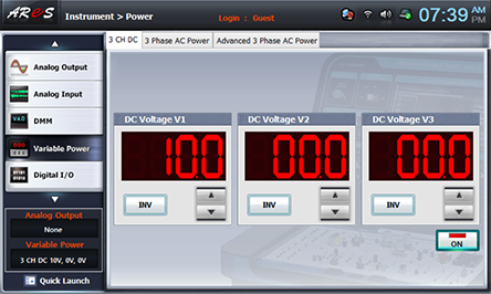
- 1Choose variable power at left menu of Touch LCD panel and set up at 3 CH DC with for DC Voltage V1 to become 10V.
Click , and supply the output of DC 10V to the circuit.
Turn on the SW3.
- 2Choose dmm at the left menu of Touch LCD panel and click .
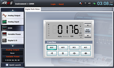
Record the measured value(A point) in the relevant column of table 10-5.
Plug out the red lead wire connected between High terminal of Multimeter on front panel and the base terminal of TR3 of Block c on M10 board and change the connection to the collector of TR3(B point), the base of TR4(C point), the collector of TR4(D point) and the emitter of TR5(E point) and measure the voltage and record the result in the relevant column of table 10-5.
- 3Execute the process 2) above with the mouth being approached to the mic and record the result in the relevant column of table 10-5.
- 4After the measurement, choose variable power at the left menu of Touch LCD panel and click to cut off the power supply.