PART7Basic Circuit of Semiconductor
Experiment 10 :Chacracteristic of UJT
Theory
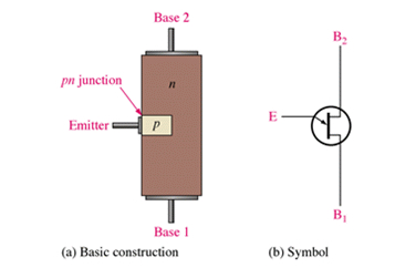
UJT transistor, as in fig.7-40, is composed of a stick semiconductor whose resitivity is high and a electrode attached to the semiconductor in order to inject the carrier in the middle, so one junction is generated. N type semiconductor becomes the base and three electrodes, that is, the first base B1, the second base B2, and the emitter E are included.
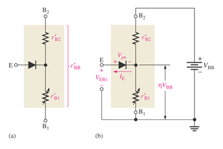
The single junction between B1 and B2 usually works as the resistance. This resistance is the base resistance RBB and it has the resistance value of 9.1kΩ range.
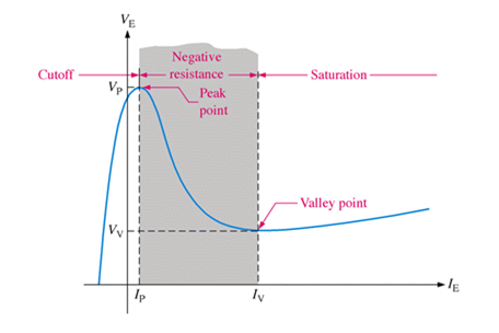
It is operated by changing the conductivity between B1 and B2 by the positive hole injected from the emitter and generating negative resistance, and is called double base diode. The reasons that it is used as the trigger generator are that its rated peak current is big, the trigger voltage is stable, the power consumption is small, its size is small and the operation is simple.
Total resistance between base terminals r'BB =r'B1 +r'B2
![V _{r 'B1} =[ {r' _{B1}} over {r' _{B2} } ]V _{BB}](../image/part7/formal7.18.gif)
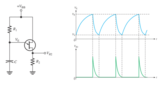
Turn On and Turn Off Condition
- Turn On Condition : VBB-VP>IPR1 , Turn Off Condition : VBB-VV>IVR1
- Range of R1 for Proper Turn On and Turn Off: :

The cycle of pulse changes in wide range according to the value of R1, C, and for a stable oscillation, the maximum and minimum value of R1 should be limited to certain value(2kΩ~3MΩ).
Experiment Process
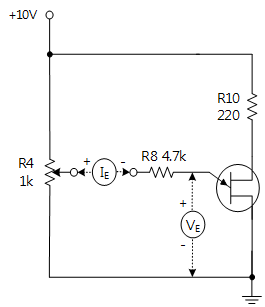
1. To experiment the characteristic of UJT, make a connection as in fig.7-44 using Block d of M07 and supply DC 10V power.
- VR4 is used to adjust the emitter voltage(VE) between E and B1. R11 is the emitter series resistance and R10 is current limiting resistance.
2. Measure the emitter voltage(VE) by connecting the voltmeter between E and B1.
- Observe the change of emitter current(IE) by emitter voltage(VE) when turning VR4 to the right slowly as the voltage given in table 7-15 and record the result in the relevant column of the table.
- Measure and record the peak point voltage(VP) when the emitter voltage(VE) suddenly decreases.
- If you turn VR4 to the right slowly, the emitter voltage(VE) passes the peak point voltage(VP) and reaches the minimum value. The emitter voltage(VE) here is the valley point voltage(VV).
- Record the valley point voltage(VV).
3. Calculate the intrinsic standoff ratio of UJT η by the following calculation

(Here, VE = 0.7V)
Experiment 7-10.1 UJT Characteristic Measurement (In Block d of M07, compose a circuit as infig.7-44.)
1.Connection(Block d of M07)
1.Circuit Connection
In Block d, connect between B1 polarity terminal of UJT and the earthing terminal with yellow line.
In Block d, connect between B2 polarity terminal of UJT and lower terminal of R10 with yellow line.
2.Power Connection
Connect between V1 terminal of Variable Power on the left of M07 board and V+ terminal of Block d with red line, and between COM terminal and the earthing terminal with black line.
3.Measuring Instrument Connection
Ammeter Connection
UJT emitter current(IE) measurement : Measure by using the current measurement function of separate Digital Multimeter. Conenct the red lead wire of Digital Multimeter to center terminal of VR4 of Block d and the black lead wire to the terminal connected to the bottom of R11.
Voltmeter Connection
Measuring emitter voltage(voltage between R11’s both ends(VE)): Connect between High terminal of Multimeter on the front panel and the terminal connected to SW5 of Block d with red line, and between Low terminal and the earthing terminal with black line.
2.Wiring Diagram
3.Measurement
- 1Choose variable power at the left menu of Touch LCD panel and set up at 3 CH DC to make V1 as 10V with .
Click to supply DC 10V output to the circuit.
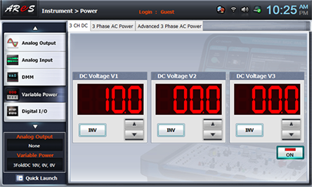
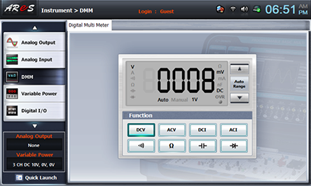
- 2Choose dmm at the left menu of Touch LCD panel, and click .
- 3Turn on SW5.
- 4Observe the change of emitter current(IE) by emitter voltage(VE) when turning VR4 to the right slowly as the voltage given in table 7-15 and record the result in the relevant column of the table.
Choose dmm at the left menu of Touch LCD panel and record the measured value of emitter voltage(VE) in the relevant column.
Record the value of UJT emitter current(IE) measured by separate digital multimeter in the relevant column. .
- 5After the measurement, choose variable power at the left menu of Touch LCD panel and click to cut off the power supply.
Experiment Result Report
1. Experiment Result Table
2. Review and Explanation
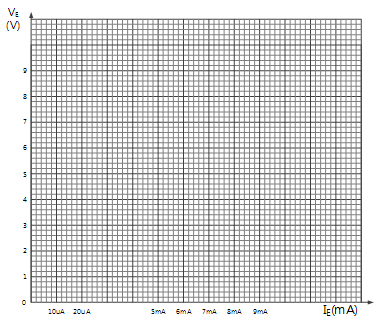
1) In table 7-15 above, draw a characteristic curve between emitter voltage[VE] and emitter current[IE].
2) How much is the peak point voltage(VP)?
3) How much is the valley point voltage(VV)?
4) Calculate the intrinsic standoff ratioη by the following formula.

(Here, VE = 0.7V)


