


PART11Oscillator Circuit
Experiment 3 :Astable Multivibrator Magnetism Experiment
Theory
Astable multivibrator is a circuit that has no stable state, and is used as square wave generation circuit or time generator. This is the oscillation circuit that changes between set state and reset state in turn, and can be composed as below using a transistor.
Fig.11-4 is an astable multivibrator circuit.
When the power is first applied, one transistor operates faster than the other because of the difference between components in two parts of symmetrical circuit.
The reason that the potential falls at the collector of the first transistor is because it moves toward the cutoff of the base of the other transistor connected to the capacitor. The potential rising at the collector of the second transistor strengthens the initial indication of the base of the first transistor connected reversely to the capacitor. This cycle saturates the first transistor very quickly and the other transistor is cutoff by the regeneration feedback. However, the state does not become stable.
If TR4 is saturated, TR3 is cutoff. When TR4 is conducted, the voltage falls at VC4 so the base of TR3 becomes – potential. The – charged at C7 is discharged through R12 until VB3 reaches 0.7V and TR3 starts conducting. When the potential falls at VC3, C6 is conducted and TR4 is cutoff. When the potential rises at VC4, it is conducted through C7 and TR3 is saturated fast by the regeneration feedback.
The reason that the potential of VC3 falls suddenly is because of the – potential of the base of TR4 and TR4 is cutoff. If C6 is charged, it is discharged immediately through R11 and C7 is charged through R14. When the base of TR4 reaches the conductance potential, TR4 operates and completes half-wave. When TR$4 is conducted, TR3 is cutoff and the potential is reversed for this half-wave. That is, the circuit oscillates continuously through the cycle that oscillates endlessly the complementary square wave to VC3 and VC4.
The astable multivibrator repeats the operation above from the moment the power is applied and generates square wave of constant cycle.
Experiment Process
1. Using Block c of M11 board, make a connection as in fig.11-5.
2. Make the output power of DC power supplier as 10V and connect it to the circuit.
3. Measure the waveform of base and collector terminals of TR3 and TR4 using the oscilloscope and record the result in the relevant column of table 11-3.
4. Calculate the frequency characteristic of the oscillator using the formula below.
5. Turn off the power, change the wiring diagram as in fig.11-6 and repeat the experiment above.
tab1
Experiment 11-3.1
Astable MV Experiment Circuit 1
1.Connection(Block c of M11)
1.Circuit Connection
In Block c of M11 board, connect between the lower terminal of R9 and the collector terminal of TR3 with yellow line.
In Block c of M11 board, connect between the lower terminal of R11 and the base terminal of TR4 with yellow line.
In Block c of M11 board, connect between the lower terminal of R12 and the base terminal of TR3 with yellow line.
In Block c of M11 board, connect between the lower terminal of R14 and the collector terminal of TR4 with yellow line.
2.Power Connection
Connect between V1 terminal of Variable Power on the left of M11 board and V+ terminal of Block c with red line, and between COM terminal and the earthing terminal with black line.
3.Measuring Instrument Connection
Measuring base and collector waveform of TR3
On the front panel, connect between A+ terminal of Signal Input CH A and the base terminal of TR3 of Block c on M11 board with red line, and between A- terminal and the earthing terminal of Block c with black line.
On the front panel, connect between B+ terminal of Signal Input CH B and the collector terminal of TR4 of Block c on M11 board with red line, and between B- terminal and the earthing terminal of Block c with black line.
2.Wiring Diagram
flash
3.Measurement
- 1Choose variable power at left menu of Touch LCD panel and set up at 3 CH DC for DC Voltage V1 to become 10V.
Click , and supply the output of DC 10V to the circuit.
Turn on the SW4, 5.
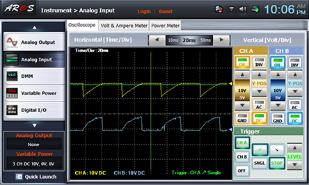
- 2Choose analog input at the left menu of Touch LCD panel, choose Oscilloscope tab to observe the waveform of CH A(base of TR3), CH B(collector of TR3) and draw the result in the relevant column of table 11-3.
- 3For <Measuring base and collector waveform of TR4>, connect the measuring instrument as below.
On the front panel, connect between A+ terminal of Signal Input CH A and the base terminal of TR4 of Block c on M11 board with red line, and between A- terminal and the earthing terminal of Block c with black line.
On the front panel, connect between B+ terminal of Signal Input CH B and the collector terminal of TR4 of Block c on M11 board with red line, and between B- terminal and the earthing terminal of Block c with black line.
Observe the waveforms of CH A(base of TR4), CH B(collector of TR4) and observe the result in the relevant column of table 11-3.

Astable MV Experiment Circuit 2
4.Connection(Block c of M11)
1.Change the Circuit Connection as below.
lock c of M11 board, connect between the lower terminal of R9 and the collector terminal of TR3 with yellow line.
In Block c of M11 board, connect between the lower terminal of R10 and the base terminal of TR4 with yellow line.
In Block c of M11 board, connect between the lower terminal of R13 and the base terminal of TR3 with yellow line.
In Block c of M11 board, connect between the lower terminal of R14 and the collector terminal of TR4 with yellow line.
5.Wiring Diagram
flash
6.Measurement
위 Execute the process 3. Measurement> 2), 3) above and record the result in the relevant column of table 11-4.
- 1After the measurement, choose variable power at left menu of Touch LCD panel, and click to cut off the power supply.