


PART1R, L, C Circuit
Experiment Purpose
- 1.Learns the methods for resistor and Ohm’s law.
- 2.Learns how to measure DC and AC voltage/current/power.
- 3.Learns superposition/Thevenin/Norton’s theorem.
- 4.Learns AC(RC/RL/RLC) circuit.
Experiment 1 :DC Voltage Measurement
Theory
Generally, in case of DC voltmeter, the FS(Full Scale) sensitivity of current meter is usually from 50 A to 1mA, and its internal resistance is around 100Ω ~ 1KΩ. When the input voltage is VT, the voltage of voltmeter V1, the voltage of multiplier’s both ends V2, VT=V1+V2. And if the internal resistance of voltmeter is Rm, and the resistance of multiplier is RM, V1 and V2 can be expressed as the relational expression below.
Therefore, if the voltmeter indicates V1 value, the actual measured voltage can be earned by multiplying the magnification of measuring range.
Experiment Process
1. In M01 Module, connect between V1 of Variable Power, COM terminal and High, Low terminals of Multimeter and compose a circuit as in fig.1-2.
2. Record the measured voltage at the voltmeter in the relevant column of table 1-1 when changing the output voltage from power supply as 5V, 9V, 12V, 15V, 20V.
tab1Experiment 1-1.1 Using M01, compose a circuit as in fig.1-2.
1.Connection(M01 Module)
1.Connect the measuring module(ARES-EI-M01) to the platform.
2.Connection between Power and Measuring Instrument
In M01 module, connect between V1 terminal of Variable Power and High terminal of Multimeter on the front panel with red line, and between COM terminal and Low terminal with black line.
2.Wiring Diagram
flash
3.Measurement
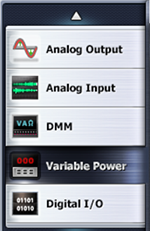
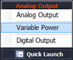
- 1Choose at left menu of Touch LCD panel variable power.
- 2Choose 3 CH DC tab and click at DC Voltage V1 to set up 5V.
Double click DC Voltage V1, click 0 , 5 and ok using Quick Number Keypad, and the number is set up directly.
- 3Click , then it is as the fig. below, and the output of DC 5V is inputted to the circuit.

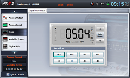
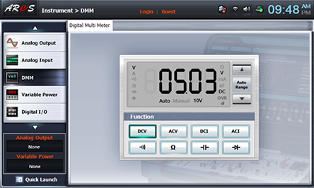
- 4Click dmm at left menu, then Digital Multimeter window appears. If you click here, the voltage value is displayed. Record it in the measured value for straight polarity in table 1-1.
- 5Click quick launch at bottom of left menu on Touch LCD panel, choose Variable Power and click of DC Voltage V1 to change it as 9V, 12V, 15V, 20V and record the measured value in Digital Multi Meter in straight polarity measurement value of table 1-1.

- 6Change the connection location between red line and black line and execute the process 2)-5) and record the measured voltage value in reverse polarity measurement value of table 1-1.
- 7After the measurement, click to cut off the output of Variable Power.
Experiment 1-1.2 Using M01, compose a circuit as in fig.1-2.
3. In M01 Module, connect between +5V, +15V, GND, -15V voltage with High, Low terminals of Multimeter and record the measured voltage in the relevant column of table 1-1.
1.Connection(M01 Module))
1.Connection between Power and Measuring Instrument
In M01 module, connect between +5V terminal of Fixed Power and High terminal of Multimeter on the front panel with red line, and between GND terminal and Low terminal with black line.
2.Wiring Diagram
flash
3.Measurement
- 1If you click dmm at left menu, Digital Multi Meter window appears and if you click here, the voltage value is displayed. Record it in the relevant column of table 1-1.
- 2Measure by following the connection of Fixed Power in table 1-1 and record the result in the relevant column of table 1-1.