


PART1R, L, C Circuit
Experiment 7 :Serial/Paralle Combination Circuit and Kirchhoff’s Law
Theory
Kirchhoff’s law explains the relationship between current and voltage in a complex circuit that has more than two voltage sources, and is classified into the law of voltage and of current.
Kirchhoff’s Law of Voltage
In a circuit having multiple voltage sources, if a closed circuit is composed for each voltage source, the sum of increasing voltage and decreasing voltage in the closed circuit is same. That is, the sum of all voltages within the closed circuit is “0”.
In fig.1-9(a), assuming that the current flows clockwise, EB is the increasing voltage and ER1, ER2 are decreasing voltages. Therefore, EB=ER1+ER2, that is, EB-ER1-ER2=0.
Kirchhoff’s Law of Current
At each node of parallel circuit, the sum of incoming current is same as that of outgoing current.
In fig.1-9(b), the current coming into node A is IT, and the currents going out are IR1, IR2. Therefore, IT=IR1+IR2, that is, IT-IR1-IR2=0.
Experiment Process
1. In Block b of M01 module, connect the voltmeter at both ends of R3, VR1 and compose a circuit as in fig.1-10. (Here, the knob of VR1 should be located at the center.)
2. Record the measured voltage of each voltmeter in the relevant column of table 1-6. And calculate the voltage value according to given formula and record the result in the relevant column.
3. Measure the resistance value of R3, VR1 and record the result in the relevant column.(To measure the resistance value, remove the power and voltmeter within the circuit and measure directly the both ends of each resistance with the ohmmeter.)
tab1Experiment 1-7.1 In Block b of M01, compose a circuit as in fig.1-10.
1.Connection(Block b of M01)
1.Circuit Connection
Connect 1, 2 terminals of VR1 on the left of Block a with yellow lines.
Connect between terminal 1 of VR1 on the left of Block a and the left terminal of VR1 of Block b with yellow line, and between terminal 3 of VR1 on the left of Block a and the right terminal of VR1 of Block b with yellow line.
2.Power Connection
Connect between V1 terminal of Variable Power on the left of M01 board and upper terminal of R3 of Block b with red line.
Connect between COM terminal of Variable Power on the left of M01 board and left terminal of VR1 of Block b with black line.
3.Measuring Instrument Connection
V1 Voltage Measurement
Connect between upper terminal of R3 of Block b and A+ terminal of Signal Input CH A on front panel with red line, and between lower terminal of R3 and A- terminal with black line.
V2 Voltage Measurement
Connect between right terminal of VR1 of Block b and B+ terminal of Signal Input CH B on front panel with red line, and between left terminal of VR1 and B- terminal with black line.
2.Wiring Diagram
flash
3.Measurement
- 1Make the knob of VR1 be located at the center.
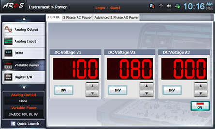
- 2Choose variable power at left menu of Touch LCD panel.
- 3Choose 3 CH DC tab and click at DC Voltage V1 to set up 10V.
Click , and then the output of DC 10V is inputted to the circuit.
- 4Choose analog input at left menu of Touch LCD panel and click Volt & Ampere Meter tab. Click , , for CH A and CH B each.
Record the measured values in CH A and CH B in V1 and V2 of table 1-6. Here, CH A is voltage V1 and CH B voltage V2.
- 5Execute the process above when turning VR1 counterclockwise to minimum and when turning it clockwise to maximum and record the measured result in the relevant column of table 1-6.
Resistance Measurement
1. Measurement
- 1) Remove the red line connected to V1 terminal of Variable Power on left of M01 module.
- 2) Choose dmm at left menu of Touch LCD panel and click at Digital Multimeter window.
- 3) Connect between High terminal of Multimeter on front panel and upper terminal fo R3 of Block b with red line, and between Low terminal and lower terminal of R3 with black line, and record the measured value in R value of Circuit in table 3-6. (R1 Measurement)
- 4) Pull out two lines connected to upper terminal and lower terminal of R3 and connect them to right terminal and left terminal of VR1, measure VR1 and record the result in table 1-6.
- 5) Measure total combined resistance and record it in the relevant column of table 1-7.
Wiring Diagram
flash
Experiment Process
1. In Block b of M01 module, connect the ammeter in order to measure the current flowing through R2 and R3 and compose a circuit as in fig.1-11. (Here, the knob of VR1 should be located at the center.)
2. Record the measured current of each ammeter in the relevant column of table 1-7. And calculate the current value according to given formula and record the result in the relevant column.
3. Measure the resistance value of R2, R3, VR1 and record the result in the relevant column.(To measure the resistance value, remove the power and voltmeter within the circuit and measure directly the both ends of each resistance with the ohmmeter.)
tab2Experiment 1-7.2 In Block b of M01, compose a circuit as in fig.1-11
1.Connection(Block b of M01)
1.Circuit Connection
Connect 1, 2 terminals of VR1 on the left of Block a with yellow lines.
Connect between terminal 1 of VR1 on the left of Block a and the left terminal of VR1 of Block b with yellow line, and between terminal 3 of VR1 on the left of Block a and the right terminal of VR1 of Block b with yellow line
2.Power Connection
Connect between V1 terminal of Variable Power on the left of M01 board and upper terminal of Block b with red line.
Connect between COM terminal of Variable Power on the left of M01 board and lower terminal of R2 1k of Block b with black line.
3.Measuring Instrument(Ammeter) Connection
A1 Current Measurement
Connect between upper terminal of Block b and mA/A terminal of Multimeter on front panel with red line, and between upper terminal of R21k and Low terminal with black line.
Connect between upper terminal of block b and upper terminal of R3 1k with yellow line.
A2 Current Measurement
Connect between upper terminal of Block b and mA/A terminal of Multimeter on front panel with red line, and between upper terminal of R3 1k and Low terminal with black line.
Connect between upper terminal of block b and upper terminal of R2 1k with yellow line.
2.Wiring Diagram
A1 Current Measurement
flash
A2 Current Measurement
flash
3.Measurement
- 1Choose variable power at left menu of Touch LCD panel.
- 2Choose 3 CH DC tab and click at DC Voltage V1 to set up 10V.
Double click DC Voltage V1, click 1, 0 and ok using Quick Number Keypad, and the number is set up directly.
Click , and then the output of DC 10V is inputted to the circuit.
- 3Connect as 1. Connection>Ammeter Connection><A1 Current Measurement> and click dmm at left menu, then Digital Multimeter window appears, and if you click , the current value and direction of A1 apepar. Record it in the relevant column of table 1-7.
- 4Connect as 1. Connection>Ammeter Connection><A2 Current Measurement>, and record the current value and direction indicated in Digital Multimeter window in the relevant column of table 1-7.
- 5Execute the process above when turning VR1 counterclockwise to minimum and when turning it clockwise to maximum and record the measured result in the relevant column of table 1-7.
Resistance Measurement
1. Measurement
- 1) Remove the red line connected to V1 terminal of Variable Power on the left of M01 module.
- 2) Choose dmm at left menu of Touch LCD panel and click at Digital Multimeter window.
- 3) Connect between High terminal of Multimeter on front panel and upper terminal fo R3 of Block b with red line, and between Low terminal and lower terminal of R3 with black line, and record the measured value in R value of Circuit in table 1-7. (Measure and record R2 in the same way.)
- 4) Pull out two lines connected to upper terminal and lower terminal of R3(R2) and connect them to right terminal and left terminal of VR1, measure VR1 and record the result in table 1-7.
- 5) Measure total combined resistance and record it in the relevant column of table 1-7.
Wiring Diagram
flash