


PART9Electrical Acoustic Amplification Circuit
Experiment 2 :Wheatstone Bridge
Theory
The wheatstone bridge is used to measure the resistance more precisely. This is the device to measure the unknown resistance precisely by using the known resistance. In the fig. above, P, Q are already known and X is the variable resistance whose value can be read. R is the unknown resistance to be measured. Close the switch S and adjust the variable resistance X so that the current does not flow to the galvanometer. Then the potential difference of c and d becomes same so IRP =IPQ ,IRX =IRR , and P and X are same I1, and Q and R are same I2 so RP R=RQ RX is established. That is, the resistance values of RP ,RQ ,RXare already known so the value of the unknown resistance R is as below.
This wheatstone bridge uses the zero method, which adjusts X properly, makes the current not flow through the galvanometer G and finds the balancing condition. When the galvanometer is connected between c and d, if the needle of the galvanometer points at 0, t means the current does not flow between these and a point and b point become equipotential points.
Experiment Process
1. Using Block a of M09, make a connection as in fig.9-5.
2. Make the power of power supplier as DC 5V and connect to the circuit.
3. Connect the R1 resistance to RX resistance of the bridge circuit, turn VR and observe the value of galvanometer.
- Turn VR slightly and locate the galvanometer at 0. When it is balanced, turn off the power switch and measure the resistance of VR and record the result in the relevant column of table 9-2.
4. Remove R1, locate R2, R3 resistance at RX, repeat the experiment above, turn off the power switch and measure the resistance of VR and record the result in the relevant column of table 9-2.
tab1Experiment 9-2.1
1.Connection(M09의 block a)
1.Circuit Connection
In Block a of M09 board, connect between the left terminal of R1 and the terminal where RX and R4 are contacted with yellow line.
In Block a of M09 board, connect between the right terminal of R1 and the terminal where RX and VR are contacted with yellow line.
2.Power Connection
Connect between +5V terminal of Fixed Power on the left of M09 board and V+ terminal of Block a with red line, and between GND terminal and the earthing terminal with black line.
3.Measuring Instrument Connection
Galvanometer
Connect between the + terminal of separate galvanometer and the terminal where RX and VR are contacted with red line, and between – terminal of the galvanometer and the terminal where R4 and R5 are contacted with black line.
2.Wiring Diagram
flash
3.Measurement
- 1Turn VR slightly and locate the galvanometer at 0.
Remove the red line connected between +5V terminal of Fixed Power on the left of M09 board and V+ terminal of Block a.
The power must be cut off when measuring the resistance.
- 2VR Resistance Measurement
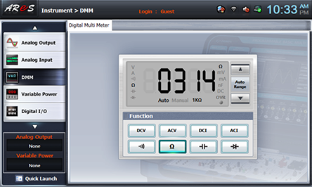
Choose dmm at the left menu of Touch LCD panel and click .
Connect between High terminal of Multimeter on the front panel and the upper terminal of Vr of Block a on M09 board with red line, and between Low terminal and the earthing terminal of Block a with black line.
Record the measured resistance value of VR in the relevant column of table 9-2.
After the measurement of VR resistance is finished, remove the line connected to the multimeter.
Connect between +5V terminal of Fixed Power on the left of M09 board and V+ terminal of Block a with red line again.
- 3Remove R1, locate R2 and R3 resistance at RX, execute the process 1), 2) above and record the result in the relevant column of table 9-2.
- 4After the measurement, remove the red line connected between +5V terminal of Fixed Power on the left of M09 board and V+ terminal of Block a and cut off the power supply.