


PART6Characteristic of Coil
Experiment 3 :Magnetic Flux Detection
Theory
The magnetic flux(Φ) is the shortened word for the flux of line of magnetic force, and as in fig.6-8(a), it means the number of line of magnetic force that passes the material vertically. If B is the number of line of magnetic force(in other words, magnetic flux density) per unit area(1㎡) and A is the area of the side, total number of line of magnetic force becomes Φ=BA.
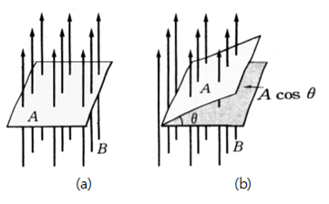
Meanwhile, if the side is tilted as much as θ to the side that is vertical to the line of magnetic force, as in fig.(b), the area of the side which is vertical to the line of magnetic force becomes Acosθ. Therefore, it becomes Φ=BAcosθ.
One thing to be noteworthy here; what degree the angle θ will be in the left fig.(a)? Visually, it seems as 90°. However, it is 0°. Since the side which is vertical to the line of magnetic force becomes the standard, the area A in fig.(a) is the standard itself and the angle is 0°.
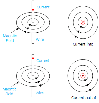
When you indicate the direction of current or magnetic field, the shapes such as ⊗ or ⊙ are used, and when ⊗, the shape of screw’s head is turned to the right, the screw is screwed in and when you see ⊙ , the shape of below from the bottom, the screw is screwed out. Therefore, ⊗ indicates “In-Direction” and ⊙ indicates “Out-Direction”. Seen from above in fig.(A), the line of magnetic force comes out so it should be indicated as ⊙. When the object on the area A is seen from the bottom in fig.(a), the line of magnetic force goes into the object A so it should be indicated as ⊗.
Experiment Process
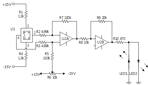
1. In Block c of M06 board, make a connection as in fig.6-10.
2. Connect ±15V power to the circuit.
3. Adjust R6 and set up the output of U2A as 0V. (pin 7 of U2)
4. Approach the magnet to U1, and measure the output voltage of U2b with the voltmeter.
- Measure the change of U2B with changing the size of magnetic field and polarity and record the result in the relevant column of table 6-3.
5. Record the state of LED1 and LED2 in the relevant column of table 6-3.
tab1Experiment 6-3.1
1.Connection
1.Power Connection
Connect between Fixed Power +15V terminal on the left of M06 board and +15V terminal of Block c with red line, and between -15V terminal and -15V terminal of Block c with blue line.
GND is connected internally.
2.Measuring Instrument Connection
Offset Voltage Measurement
Connect between A+ terminal of Signal Input CH A on front panel and pin 7 of U2 with red line, and between A- terminal and GND terminal of Fixed Power with black line.
Output Voltage Measurement
Connect between B+ terminal of Signal Input CH B on front panel and upper terminal of LED1 of Block c with red line, and between B- terminal and GND terminal of Fixed Power with black line.
2.Wiring Diagram
flash
3.Measurement
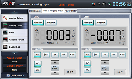
- 1Click analog input at the left menu of Touch LCD panel, choose Volt & Ampere Meter tab, and choose , , at CH A and CH B.
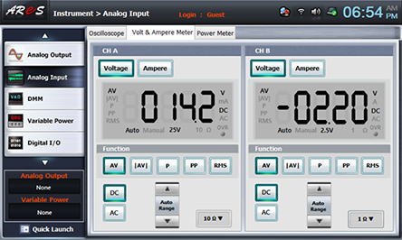
- 2Adjust the variable resistance R6 of Block c and set up the output of U2A(CH A) as 0V.
Record the state of LED1 and LED2 in the relevant column of table 6-3.
- 3Approach the magnet to U1, and measure the output voltage of U2b with the voltmeter and record the result in the relevant column of table 6-3.
Measure the change of U2B with changing the size of magnetic field and polarity and record the result in the relevant column of table 6-3.
Record the state of LED1 and LED2 in the relevant column of table 6-3.