PART6Characteristic of Coil
Experiment 2 :Mutual Inductance
Theory
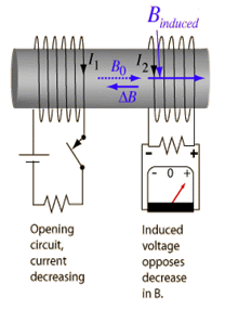
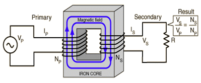
Mutual inductance means the phenomenon that the magnetic field made at the primary coil changes and the current is induced to the secondary coil. When the primary and the secondary coils are put near and the current at the primary coil is changed so that the magnetic field by the coil is changed as times goes by, the induced electromotive force occurs to the secondary coil by the time-based change of magnetic flux by the primary coil.
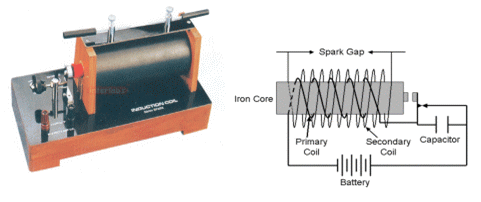
The electric energy is delivered from one place to the other leaping over the empty space. The direction of mutual induced electromotive force is as follows; when the current of primary coil increases, that of secondary coil increases in the opposite direction of the primary coil, and if the current of primary coil increases, that of secondary coil is generated in the same direction as the primary coil. The mutual inductance is used in the transformer, induction coil and so on. The induction coil is the device that gets high voltage of tens of thousands of volt in the secondary coil by interrupting the current flowing through the primary coil.
Experiment Process
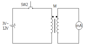
1. In Block b of M06 board, make a connection as in fig.6-7.
2. Apply DC 3V to the circuit, observe the change of ammeter when SW1 is pressed and when it is detached, and describe its cause in the relevant column of table 6-2.
- when the switch is pressed:
- when the switch is detached:
tab1Experiment 6-2.1
1.Connection
1.Power Connection
Connect between Variable Power V1 terminal on the left of M06 board and V+ terminal of Block b with red line, and between COM terminal and the earthing terminal of Block b with black line.
2.Measuring Instrument Connection
Connect between mA/A terminal of multimeter on front panel and upper terminal of OUT of Block b with red line, and between Low terminal and lower terminal of Out with black line.
2.Wiring Diagram
3.Measurement
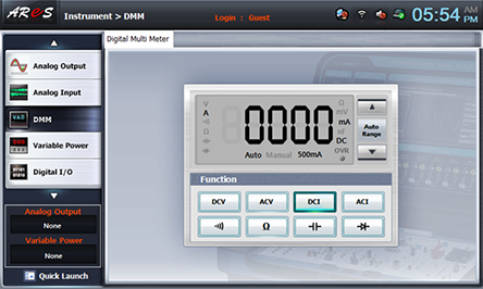
- 1Click dmm at left menu of Touch LCD panel, then Digital Multimeter window appears, and if you click here, the current value is indicated.
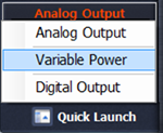
- 2Choose quick launch at bottom of left menu on front panel and click Variable Power .
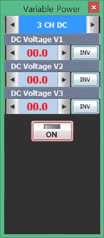
- 3Choose 3 CH DC tab and click at DC Voltage V1 and increase the voltage to become 3V.
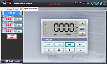
If you click , the DC output is applied to the circuit.
- 4Measure the current value and polarity indicated momentarily at DMM when the switch is pressed and when it is detached, record the result in the relevant column of table 6-2.
- 5Execute the process above by changing the DC voltage as 6V, 9V, 12V.
- 6After the measurement, click to cut off the voltage applied to the circuit.


