


PART10Characteristic Circuit of Electric Element
Experiment 4 :Experiment for Temperature Control Switch Circuit
Experiment Process
1. Using Block b of M10 board, make a connection as in fig.10-4.
2. Make the output power of DC power supplier as 5V.
3. Supply AC 9V to lamp 1 and lamp 2 from AC power supplier.
4. Turn VR2 and turn off lamp 1 and lamp 2. Record how SCR operates here.
5. Approach the heated iron to the thermistor and record the state of lamp and that of SCR.
6. Detach the heated iron from the thermistor and record the state of lamp and that of SCR after several seconds.
tab1Experiment 10-4.1
1.Connection(Block b of M10)
1.Circuit Connection
Connect the terminal to which VR2-SW2 of Block b is connected and the terminal connected to SCR gate with yellow line.
Connect the terminal to which R5-R6 of Block b is connected and the terminal connected to SCR cathode with yellow line.
2.Power Connection
DC Power Connection
Connect between +5V terminal of Fixed Power on the left of M10 board and V+ terminal of Block b with red line, and between GND terminal and the earthing terminal with black line.
AC Power Connection
Connect between V1 terminal of Variable Power on the left of M10 board and the right terminal of D2 of Block b with red line, and between V2 terminal and the right terminal of D3 of Block b with red line. Connect between COM terminal and 0 terminal of Block b with black line.
2.Wiring Diagram
flash
3.Measurement
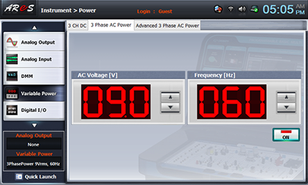
- 1Choose variable power at left menu of Touch LCD panel and set up at 3 Phase AC with for AC Voltage to become 9V.
Click , and supply the output of AC 9V to the circuit.
Turn on the SW2.
Turn VR2 and turn off lamp 1 and lamp 2. Record how SCR operates here in the relevant column of table 10-4.
Approach the heated iron to the thermistor and record the state of lamp and that of SCR in the relevant column of table 10-4.
Detach the heated iron from the thermistor and record the state of lamp and that of SCR after several seconds in the relevant column of table 10-4.
- 2After the measurement, choose variable power at the left menu of Touch LCD panel and click to cut off the power supply.