


PART4Transformer
Experiment 2 :Autotransformer
Theory
Fig. 4-6 shows an autotransformer. Coil is wound around the core and one tab is installed in the middle of the coil. If the AC voltage is added to the A-C terminal, the current flows so the magnetic field around the core is changed. And the output voltage of B-D terminal is in direct proportion to the number of coil between B-D divided by that between AC. So, if B-D is 2000 times and A-C is 100 times and 12V is added between A-C in table 4-6, the output will be 240V.
If the lead wire B is connected to sliding contact, the output voltage between B-D may change when the sliding contact changes. This transformer is suitable for the experiment which needs variable AC voltage. An autotransformer like this which can be used commercially is called Variac
Experiment Process

Caution
- 1. Compose a circuit while the input power is OFF.
- 2. Do not plug in or out the connection cord while the power is ON.
- 3. Do not touch the non-insulated conductor of the transformer.
Experiment 4-2.1 In Circuit-2 of M-04, compose a circuit as in Fig. 4-7
1.Connection(In Circuit-2 of M-04, compose a circuit as in Fig. 4-7)
1.Power Connection
Connect between V1 terminal of Variable Power and 2a terminal of Circuit-2 with red line, and between com terminal and 2b terminal with black line.
2.Measuring Instrument Connection
Connect between High terminal of Multimeter on the front panel and 2c terminal of Circuit-2 with red line, and between Low terminal and 2d terminal with black line.
2.Wiring Diagram
flash
3.Measurement
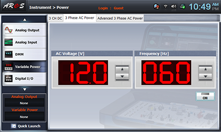
- 1Choose variable power at the left menu of Touch LCD panel and choose 3 Phase AC Power tab. Click to make 12.0V and click , then AC 12V will be output.
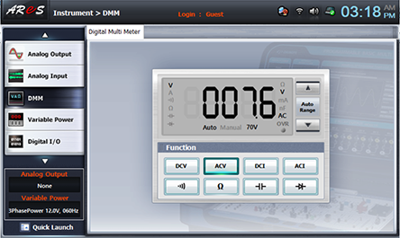
- 2Choose dmm at the left menu of Touch LCD panel.
If you click at Function of Digital Multi Meter window, the voltage of Tap-1(between 2c-2d) is measured. Record it in the relevant column of table 4-2.
Connect the red line, which is connected to 2c terminal of Circuit-2, to 2e terminal, measure the voltage of Tap-2(between 2e-2f) and record it in the relevant column of table 4-2.
Connect the red line, which is connected to 2c terminal of Circuit-2, to 2e terminal, measure the voltage of Tap-3(between 2g-2h) and record it in the relevant column of table 4-2.
- 3When the primary input voltage is 10V
Choose variable power at the left menu of Touch LCD panel and click to make it 10.0V.
Execute Measurement 2) process to measure the voltage and record it in the relevant column of table 4-2.
Execute the same process with 8V, 6V of primary voltages and record the result in the relevant column of table 4-2.
4.Calculation
1. In the autotransformer, if the turn number per 1V is 17T, calculate the turn number for each voltage.
Experiment Result Report
1. Experiment Result Table
2. Review and Explanation
1) Calculate the turn number for each voltage when the autotransformer is in 17T/1V condition.
17T×12V = 204T
Tap 1 = 17T×7.6V= 129.2T
Tap 2 = 17T×6.4V= 108.8T
Tap 1 = 17T×4.0V= 68T