


PART13Fundamental Logic Circuit
Experiment 4 :NOT Gate (INVERTER)
Theory
NOT gate usually has one output state to one input state, and the state is opposite to each other. Fig.13-15 shows NOT gate and the truth table.
Experiment Process
1. In Circuit-4 of M13, check out the output 4b by the state of LED1 for switch S1 and record the result in table 13-6.
2. In Circuit-4 of M13, make 4g-4h terminal shorted and check out the output for the input and compare it to the output in number 1.
3. In Circuit-4 of M13, measure the output between the output terminal 4f-4j by the switch S2 of the input terminal, and compare the output value with the output in number 1.
tab1Experiment 13-4.1 NOT Gate Circuit Experiment (In Circuit-4 of M13, compose a circuit as in fig.13-18.)
Transistor NOT Circuit
1.Connection
1.Power connection is internally connected.
2.Measuring Instrument Connection
Transistor Input/Output Voltage Measurement
Connect between 4a terminal of Circuit-4 and A+ terminal of Signal Input CH A on the front panel of Multimeter with red line, and between 4j terminal and A- terminal with black line.
Connect between 4b terminal and B+ terminal of CH B with red line, and between 4j terminal and B- terminal with black line.
2.Wiring Diagram
flash
3.Measurement
- 1In Circuit-4 of M13, use the transistor NOT circuit as in fig.13-18.
In Circuit-4 of M13, check out the output 4b by the state of LED1 for switch S1 and record the result in table 13-6.
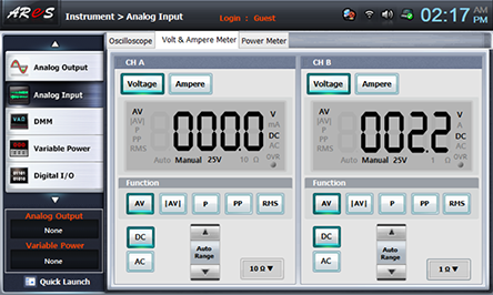
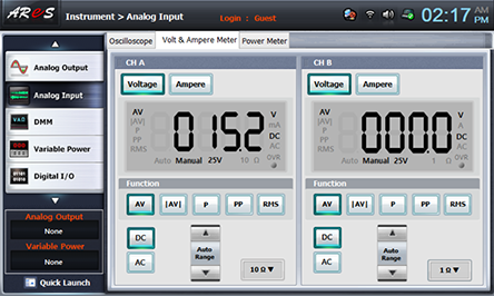
- 2Output Voltage Measurement: Choose analog input at Touch LCD panel, choose Volt & Ampere Meter tab, click , , at CH A and CH B and record the measured output voltage in the relevant column of table 13-6. (CH A = Transistor Input, CH 2 = Transistor Output)
- 3In Circuit-4 of M13, make 4g-4h terminal shorted and check out the output for the input and compare it to the output in 3. Measurement>1).
3. In Circuit-4 of M13, measure the output between the output terminal 4f-4j by the switch S2 of the input terminal, and compare the output value with the output in 3. Measurement>1).