PART5Semiconductor
Experiment Purpose
- 1.Investigate characteristics of germanium and silicon diodes
- 2.Observe the characteristic of Zener diode and learn how to use it as voltage regulator.
- 3.Investigate the characteristic of SCR.
- 4.Investigate characteristics of PNP and NPN transistor.
- 5.Investigate characteristics of J-FET and MOS-FET.
Experiment 1 :Diode Characteristic
Theory

Semiconductor diode can pass the current to one direction while it cannot to the opposite direction. This is because while the forward resistance is low, the reverse resistance is very high. All semiconductor diodes usually are one-directional.
Forward Current
As in Fig. 5-2(a), if + pole is connected to p type and - pole to n type of the p-n junction diode, it is said that the forward voltage or forward bias is applied. Here, big current, that is, forward current flows through the diode. The hole of p area flows actively to n area, and the electron of n area to p area so big current(I) can flow from p area to n area.
Reverse Current
As in Fig. 5-2 (b), if + pole is connected to n type and - pole to p type of p-n junction diode, it is said that the reverse voltage or reverse bias is applied. Here, very faint current, that is, reverse saturation current flows from n area to p area through the diode. This current reaches its maximum easily with low reverse voltage and even though the voltage gets higher it does not get bigger so is called reverse saturation current(IS).
Current Formula of Diode
The current flowing on the ideal diode can be expressed as below.
In the formula above, VT=T/11,600(26mV in room temperature), T is absolute temperature, IS is reverse saturation current and n is an integer that has 1 value to Ge and 2 value to Si. In the formula above, if V=0 then I=0, and if V > 0.1V, according to I≅Is ε40V, I increases in quotient, and if V < -0.1V, I≅Is and it is i nsaturated status. Fig. 5-3 shows the v-i characteristic of junction diode and Fig. 5-3(b) shows that of germanium diode and silicon diode. As in Fig. 5-3(b), the current increases radically at 0.7V in case of Si diode and over 0.2V in case of Ge diode. This voltage is called the cutin voltage or the threshold voltage of the diode.
Experiment Process
tab1
Experiment 5-1.1 Ge Diode DC Characteristic Measurement (in Circuit-1 of M-05, compose a circuit as in Fig. 5-3.)
When R1= 1kΩ
1.Connection(Circuit-1 of M-05)
1.Circuit Connection
Connect between 1f terminal and 1h terminal of Circuit-1 with yellow line.
2.Power Connection
Connect between A+ terminal of Signal Output on M04 board and 1a(+) terminal of Sig Input & DC Input of Circuit-1 with red line, and between A- terminal and 1b(-) terminal with black line.
3.<Measuring Instrument Connection>
Ammeter Connection
Measure by using the current measurement function of separate Digital Multimeter.
Measuring the current (IF) on the diode: Connect the red line of Digital Multimeter to 1c terminal of Circuit-1 and the black line to 1e terminal.
Voltmeter Connection
Measuring the voltage (VD) of diode’s both ends: Connect between le terminal of diode D1(Ge) and High terminal on the front panel of Multimeter with red line, and between 1f terminal and Low terminal with black line.
2.Wiring Diagram
flash
3.Measurement
- <Forward Characteristic When R1= 1kΩ>
1 Choose variable power at the left menu of Touch LCD panel, choose DC Source tab and check out if is chosen at Range.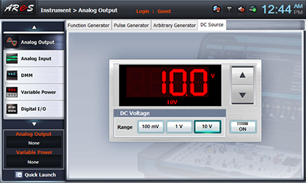
- 2Choose dmm at the left menu of Touch LCD panel and click .
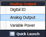
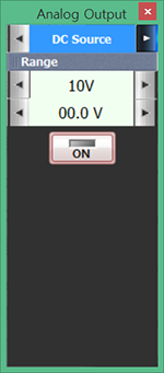
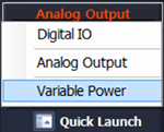
- 3Choose quick launchat lower section of Touch LCD panel, click Analog Output and click at Function to make DC Source screen appear.
Choose and click at the right of 00.0V to change the input voltage as in table 5-1, and record in the table 5-1 the forward current value (IF) indicated from the separate Digital Multimeter and the voltage value(VD) of the diode’s both ends indicated from DMM.
- 4After the measurement, click to cutoff the output and click to set up as 00.0V
- <Reverse Characteristic When R1= 1kΩ>
5 Click and click at the left to change the input voltage as in table 5-1, and record in the table 5-1 the reverse current value (IF) indicated from the separate Digital Multimeter and the reverse voltage value(VD) of the diode’s both ends indicated from DMM. - 6After the measurement, click to cut off the output.
When R2=300Ω
1.Connection(Circuit-1 of M-05)
1.Circuit Connection
Connect between 1f and 1h terminal of Circuit-1 with yellow line.
2.Power connection is same as When R1=1kΩ >1. Connection.
3.Measuring Instrument Connection
Ammeter Connection
Measure by using the current measurement function of separate Digital Multimeter.
Measuring the current (IF) on the diode: Connect the red line of Digital Multimeter to 1i terminal of Circuit-1 and the black line to 1e terminal.
Voltmeter Connection
Measuring the voltage (VD) of diode’s both ends: Connect between le terminal of diode D1(Ge) and High terminal on the front panel of Multimeter with red line, and between 1f terminal and Low terminal with black line.
2.Wiring Diagram
flash
3.Measurement
- 1It is same as When R1=1kΩ>1. Measurement, and record the measured value for the forward and reverse characteristics in table 5-1.
- 2After the measurement, click to cut off the output.
4.Calculation
1. When measuring forward characteristic of Ge diode and the input voltage is 2V, calculate the current for the case of R1(1kΩ) and that of R2(300Ω), and compare it with the current IF which flows on Ge diode.
Experiment 5-1.2 Si Diode DC Characteristic Measurement (In Circuit-1 of M-05, compose a circuit as in Fig. 5-3.)
When R1= 1kΩ
1.Connection(Circuit-1 of M-05)
1.Circuit Connection
Connect between 1l terminal and 1n terminal of Circuit-1 with yellow line.
2.Power Connection is same as Experiment 5-1.1 Ge Diode DC Characteristic Measurement>Power Connection.
3.Measuring Instrument Connection
Ammeter Connection
Measure by using the current measurement function of separate Digital Multimeter.
Measuring the current (IF) on the diode: Connect the red line of Digital Multimeter to 1d terminal of Circuit-1 and the black line to 1k terminal.
Voltmeter Connection
Measuring the voltage (VD) of diode’s both ends: Connect between lk terminal of diode D2(Ge) and High terminal on the front panel of Multimeter with red line, and between 1l terminal and Low terminal with black line.
2.Wiring Diagram
flash
3.Measurement
- 1Measure as in 5-1.1 Ge Diode DC Characteristic Measurement>Measurement and record it in table 5-1.
- 2After the measurement, click to cut off the output.
When R2=300Ω
1.Connection(Circuit-1 of M-05)
1.Circuit Connection
Connect between 1l terminal and 1n terminal of Circuit-1 with yellow line
2.Power Connection is same as Experiment 5-1.1 Ge Diode DC Characteristic Measurement>Power Connection.
3.Measuring Instrument Connection
Ammeter Connection
Measure by using the current measurement function of separate Digital Multimeter.
Measuring the current (IF) on the diode: Connect the red line of Digital Multimeter to 1i terminal of Circuit-1 and the black line to 1k terminal.
Voltmeter Connection
Measuring the voltage (VD) of diode’s both ends: Connect between lk terminal of diode D2(Ge) and High terminal on the front panel of Multimeter with red line, and between 1l terminal and Low terminal with black line.
2.Wiring Diagram
flash
3.Measurement
- 1Measure as in 5-1.1 Ge Diode DC Characteristic Measurement>Measurement and record it in table 5-1.
- 2After the measurement, click to cut off the output.
4.Calculation
1. When measuring forward characteristic of Si diode and the input voltage is 10V, calculate the current for the case of R1(1kΩ) and that of R2(300Ω), and compare it with the current IF which flows on Si diode.
Experiment 5-1.3 Ge Diode AC Characteristic Measurement (In Circuit-1 of M-05, compose a circuit as in Fig. 5-4.)
When R1= 1kΩ
1.Connection(Circuit-1 of M-05)
1.Circuit Connection
Connect between 1f terminal and 1h terminal of Circuit-1 with yellow line.
2.Power Connection
Connect between V1 terminal of Variable Power on M05 board and 1a(+) terminal of Sig Input & DC Input of Circuit-1 with red line, and between COM terminal and 1b(-) terminal with black line.
3.Measuring Instrument Connection
Ammeter Connection
Measure by using the current measurement function of separate Digital Multimeter.
Measuring the current (IF) on the diode: Connect the red line of Digital Multimeter to 1c terminal of Circuit-1 and the black line to 1e terminal.
Voltmeter Connection
Measuring VR1, the voltage of R1’s both ends: Connect between la terminal of R1 and A+ terminal of Signal Input CH A on the front panel with red line, and between 1d terminal and A- terminal with black line.
Measuring the voltage (VD) of diode’s both ends: Connect between le terminal of diode D1(Ge) and B+ terminal of Signal Input CH B on the front panel with red line, and between 1f terminal and B- terminal with black line.
2.Wiring Diagram
flash
3.Measurement
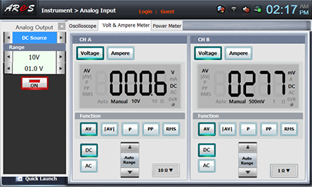
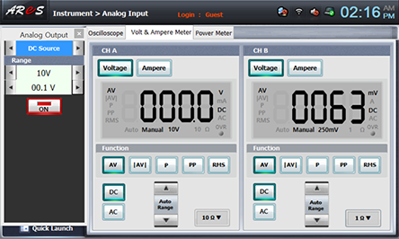
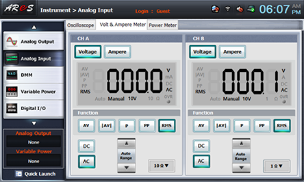
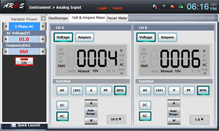
- 1Choose analog input at the left menu of Touch LCD panel, click Volt & Ampere Meter and click , , for CH A and CH B each
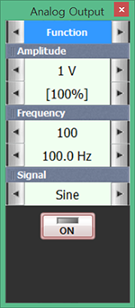
- 2Choose quick launch at lower section of Touch LCD panel, click Variable Power and click at the right of CH DC to make# Phase AC screen appear.
Choose and click at the right of 00.0V to change the input voltage as in table 5-2, and record in the table 5-2 the forward current value (IF) indicated from the separate Digital Multimeter, the voltage value (VR1) of the resistance R1’s both ends and the voltage value (VD) of the diode’s both ends.

- 3After the measurement, click to cut off the output and set up 00.0V by .
When R2=300Ω
1.Connection(Circuit-1 of M-05)
1.Circuit Connection
Connect between 1f terminal and 1h terminal of Circuit-1 with yellow line.
2.Power Connection is same as Experiment 5-1.3 Ge Diode AC Characteristic Measurement>Power Connection.
3.Measuring Instrument Connection
Ammeter Connection
Measure by using the current measurement function of separate Digital Multimeter.
Measuring the current (IF) on the diode: Connect the red line of Digital Multimeter to 1i terminal of Circuit-1 and the black line to 1e terminal.
Voltmeter Connection
Measuring VR2, the voltage of R2’s both ends: Connect between la terminal of R2 and A+ terminal of Signal Input CH A on the front panel with red line, and between 1k terminal and A- terminal with black line.
Measuring the voltage (VD) of diode’s both ends: Connect between le terminal of diode D1(Ge) and B+ terminal of Signal Input CH B on the front panel with red line, and between 1f terminal and B- terminal with black line.
2.Wiring Diagram
flash
3.Measurement
- 1It is same as Experiment 5-1.3 Ge Diode AC Characteristic Measurement> Measurement and record the measured value in table 5-2.
The measured value is the voltage value(VR2) of the resistance R2’s both ends and the voltage value (VD) of the diode’s both ends.
- 2After the measurement, click to cut off the output.
Experiment 5-1.4 Si Diode AC Characteristic Measurement (In Circuit-1 of M-05, compose a circuit as in Fig. 5-3.)
When R1= 1kΩ
1.Connection(Circuit-1 of M-05)
1.Circuit Connection
Connect between 1k terminal and 1m terminal of Circuit-1 with yellow line.
2.Power Connection is same as Experiment 5-1.3 Ge Diode AC Characteristic Measurement>Power Connection.
3.Measuring Instrument Connection
Ammeter Connection
Measure by using the current measurement function of separate Digital Multimeter.
Measuring the current (IF) on the diode: Connect the red line of Digital Multimeter to 1d terminal of Circuit-1 and the black line to 1k terminal.
Voltmeter Connection
Measuring VR1, the voltage of R1’s both ends: Connect between la terminal of R1 and A+ terminal of Signal Input CH A on the front panel with red line, and between 1k terminal and A- terminal with black line.
Measuring the voltage (VD) of diode’s both ends: Connect between lk terminal of diode D2(Si) and B+ terminal of Signal Input CH B on the front panel with red line, and between 1l terminal and B- terminal with black line.
2.Wiring Diagram
flash
3.Measurement
- 1Measure same as 5-1.3 Ge Diode AC Characteristic Measurement> Measurement and record it in table 5-2.
The measured value is the voltage value(VR1) of the resistance R1’s both ends and the voltage value (VD) of the diode’s both ends
- 2After the measurement, click to cut off the output
When R2=300Ω
1.Connection(Circuit-1 of M-05)
1.Circuit Connection
Connect between 1l terminal and 1n terminal of Circuit-1 with yellow line.
2.Power Connection is same as Experiment 5-1.3 Ge Diode AC Characteristic Measurement>Power Connection.
3.Measuring Instrument Connection
Ammeter Connection
Measure by using the current measurement function of separate Digital Multimeter.
Measuring the current (IF) on the diode: Connect the red line of Digital Multimeter to 1i terminal of Circuit-1 and the black line to 1e terminal.
Voltmeter Connection
Measuring VR2, the voltage of R2’s both ends: Connect between la terminal of R2 and A+ terminal of Signal Input CH A on the front panel with red line, and between 1k terminal and A- terminal with black line.
Measuring the voltage (VD) of diode’s both ends: Connect between lk terminal of diode D2(Si) and B+ terminal of Signal Input CH B on the front panel with red line, and between 1l terminal and B- terminal with black line.
2.Wiring Diagram
flash
3.Measurement
- 1Measure same as 5-1.3 Ge Diode AC Characteristic Measurement> Measurement and record it in table 5-2.
The measured value is the voltage value(VR2) of the resistance R2’s both ends and the voltage value (VD) of the diode’s both ends.
- 2After the measurement, click to cut off the output.
Experiment Result Report
1. Experiment Result Table
2. Review and Explanation
1) When measuring forward characteristic of Ge diode and the input voltage is 2V, calculate the current for the case of R1(1kΩ) and that of R2(300Ω), and compare it with the current IF which flows on Ge diode.
2) When measuring forward characteristic of Si diode and the input voltage is 10V, calculate the current for the case of R1(1kΩ) and that of R2(300Ω), and compare it with the current IF which flows on Si diode.
3) What is bulk resistance? Calculate the bulk resistance in the experiment above.
4) Using the measured value in table 5-1, draw a graph of a diode’s forward characteristic.
(Forward : Ge – Blue, Si – Red)
(Reverse : Ge – Blue, Si – Red)