


PART4Transformer
Experiment 3 :Transformer Load
Theory
The primary and secondary coils of the transformer have DC resistance which is in direct proportion to the thickness of the coil. Therefore, if the load current flows, the voltage drop of Rc×I occurs at the coil resistance(Rc ) and the output voltage becomes lower. Therefore, in order for the output voltage to change less by the load, the coil that has small DC resistance or thick coil should be used. To use the primary part for both 100V and 200V, the connection can be as in Fig. 4-8(a).

Also, in case of picture 4-8(b) and (c), if two 100V coils (L1,L2) are insulated, wound and connected in series as in Fig. 4-8(b), it can be used for 200V while connected in parallel as in Fig. 4-8(c), it can be used for 100V. The important thing here is the turn number and DC resistance of L1 and L2 should be same. And the start and the end of coil-winding should be clearly separated
The primary current of transformer rarely flows when there is no load on the secondary part. This is because the AC resistance increases by the secondary part having no load.
Experiment Process
tab1
Experiment 4-3.1 Transformer Load
Fig. 4-8 Circuit
1.Connection(In Circuit-3 of M-04, compose a circuit as in Fig. 4-10)
1.Circuit Connection
In Circuit-3 of M04, connect between 3b-3c terminals with yellow line.
2.Power Connection
Connect between V1 terminal of Variable Power and 3a terminal of Circuit-3 with red line, and between V2 terminal and 3d terminal with black line.
3.Measuring Instrument Connection
Connect between A+ terminal of Signal Input CH A on the front panel and 3e terminal with red line, and between Low terminal and 3j terminal with black line. (10V-0V-10V)
Connect between B+ terminal of Signal Input CH B on the front panel and 3o terminal with red line, and between B- terminal and 3r terminal with black line. (5V-0V)
2.Wiring Diagram
flash
3.Measurement
Fig. 4-10 Circuit
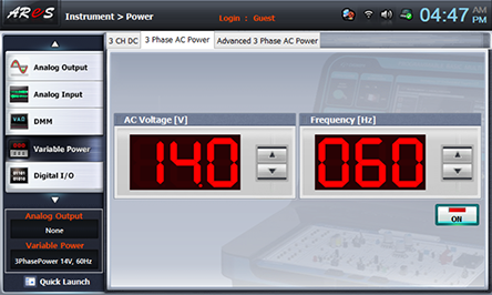
- 1Choose variable power at the left menu of Touch LCD panel and choose 3 Phase AC Power tab. Click to make 14.0V and click , then AC 24V will output at both ends of V1 and V2.
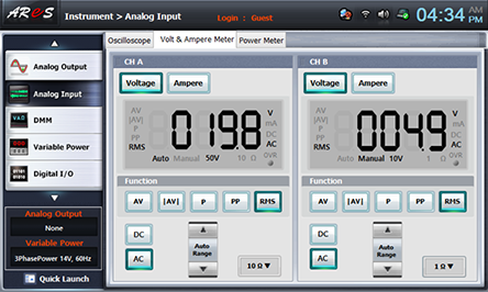
- 2Choose analog input at the left menu of Touch LCD panel
Choose Volt & Ampere Meter and choose , , at CH A and CH B each, then the measured value is indicated. Record this value in No Load column of table 4-3. Record CH A in 20V column, and CH B in 5V column.
After the measurement, choose variable power at the left menu of Touch LCD panel and click to cut off the output.
- 3Secondary Voltage Measurement with Load
Connect between 3e-3f, 3g-3i, 3j-3k terminals of Circuit-3 with yellow lines, and between 3o-3p, 3q-3r terminals with yellow lines.
Choose variable power at the left menu of Touch LCD panel and click to output AC 24V.
Choose analog input at the left menu of Touch LCD panel and record the voltage indicated in CH A and CH B in Load column of table 4-3. Record CH A in 20V column, and CH B in 5V.
After the measurement, choose variable power at the left menu of Touch LCD panel and click to cut off the output.

- 4Secondary Voltage Measurement when Overloaded
With the secondary voltage measurement with load, connect between 3m-3f, 3n-3k terminals with yellow lines, and between 3p-3s, 3q-3t terminals with yellow lines.
Choose variable power at the left menu of Touch LCD panel and click to output AC 24V.
Choose analog input at the left menu of Touch LCD panel and record the voltage indicated in CH A and CH B in Load column of table 4-3. Record CH A in 20V column, and CH B in 5V.
After the measurement, choose variable power at the left menu of Touch LCD panel and click to cut off the output.

Fig. 4-10 (a) Circuit
1.Connection(In Circuit-3 of M-04, compose a circuit as in Fig. 4-10(b)
1.Circuit Connection
In Circuit-3 of M04, connect between 3c-3a, 3b-3d terminals with yellow lines.
2.Power Connection
Connect between V1 terminal of Variable Power and 3a terminal of Circuit-3 with red line, and between com terminal and 3b terminal with black line.
3.Measuring Instrument Connection
Same as [Fig. 4-9 Circuit] Connection 3) process
2.Wiring Diagram
flash
3.Measurement
- 1Choose variable power at the left menu of Touch LCD panel and choose 3 Phase AC Power tab. Click to make 12.0V and click , then AC 12V will be output at both ends of V1 and com.
- 2Execute [Fig. 4-9 Circuit] Connection 2)~4) process and record the measured result in Fig. 4-10(a) column of table 4-3.
Fig. 4-10 (b) Circuit
1.Connection(In Circuit-3 of M-04, compose a circuit as in Fig. 4-10(b))
1.Power Connection
Connect between V1 terminal of Variable Power and 3a terminal of Circuit-3 with red line, and between com terminal and 3b terminal with black line.
2.Measuring Instrument Connection
Same as [Fig. 4-9 Circuit] Connection 3) process
2.Wiring Diagram
flash
3.Measurement
- 1Execute [Fig. 4-10 (a) Circuit] Connection 1)~4) process and record the measured result in Fig. 4-10(b) column of table 4-3.