PART11Oscillation Circuit
Experiment 5 :Crystal Oscillator
Theory
In the place where higher frequency stability than that of LC oscillator is required, crystal oscillator is used. The crystal oscillator uses the piezo electric effect of crystal instead of inductive element of LC circuit. Crystal has its own oscillation frequency but the optimal performance can be earned when coupled with outer capacitance. When bridge-surface potential is applied at both sides of the crystal, mechanical oscillation occurs, and the crystal oscillates with maximum amplitude within its inherent oscillation frequency.
The electric equivalent circuit of crystal is as fig.11-11. This circuit indicates series oscillation circuit(with loss resistance) and the crystal that is in parallel with capacitance CP. These two oscillation circuit(series and parallel) and the oscillation frequency are very close to each other(within 1%) so the impedance of crystal changes radically within narrow frequency range. This circuit is equivalent to the circuit which has very high Q, and the actual Q value of crystal can be from 20,000 to 106. This can be compared to high quality inductor and capacitor whose Q is about 1,000. The crystal has fine stability to time and temperature so the deviation of frequency can be maintained as ±0.001% within wide range of temperature. ±0.001% is equivalent to ±10ppm, and this expression is suitable for indicating very small fraction. In order for the crystal to have stability of oscillation frequency for wide temperature change, the stability of ±10ppm can be earned by put the crystal in a small temperature control oven.
The crystal is made by cutting natural quartz very minutely, and the cutting is a professional technique which determines not only the temperature and characteristic but also the inherent oscillation frequency of crystal. The crystal is used with about the frequency of 15kHz or over, and the higher the frequency is, the better the frequency stability becomes. However, in the frequency over 100MHz, the crystal gets too thin so the treatment problems can be followed.
The crystal is used instead of the inductor in the LC oscillation circuit element, and fig.11-12 is a Pierce oscillator which especially adopts crystal oscillator. When FET is used in the circuit, the load applies easily to the crystal because of the high impedance of FET, and it has good stability and Q does not decrease. This circuit is essentially same as Colpitts oscillator, but the crystal is used instead of the inductor and the divided capacitor is substituted by the intrinsic joint capacities of FET. These joint capacities normally have small values so this oscillator operates effectively in high frequency.
Special advantage of Pierce oscillator is that it is easy to change the frequency. This circuit has no tuning circuit so by inserting different crystal at X and Y point of fig.11-12, the frequency can be changed easily. This is very useful for radio transmitter which needs to be operated with multiple different frequencies.
High accuracy of digital watch depends on the high frequency precision of crystal oscillator, and the thin section of quartz has error of several seconds per 1 month.
Experiment Process
1. In Pierce oscillator as in Circuit-5 of M-11, connect C2(0.001uF), and measure and record output frequency and output voltage in table 11-5.
2. Next, measure output frequency and output voltage without connecting C2, and record the result in the relevant column of table 11-5.
tab1Experiment 11-5.1 Crystal Oscillator Experiment (Compose a circuit as in Circuit-5 of M11.)
1.Connection(Experiment Circuit-5 of M11.)
1.Power connection is internally connected.
2.Measuring Instrument Connection
Oscilloscope and Voltmeter Connection
Output Voltage Measurement Connection: Connect between 5f terminal of Circuit-5 and A+ terminal of Signal Input CH A on the front panel of Multimeter with red line, and between 5g terminal and A- terminal with black line.
2.Wiring Diagram
flash
3.Measurement
- 1Measurement of a circuit where the capacitor C2(0.001F) is connected
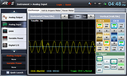
Choose analog input at front panel, draw the output wave form in oscilloscope screen, and record the output frequency and calculated frequency in the relevant columns of table 11-5. Set up the oscilloscope so that the wave form can be optimal.
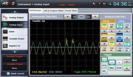
- 2Measurement of a circuit where the capacitor C2(0.001F) is not connected(Q1 Collector Output Signal)
In order not to connect the capacitor C2(0.001F) to the circuit, connect between 5e terminal of Circuit-5 and A+ terminal of Signal Input CH A on the front panel of Multimeter with red line, and between 5g terminal and A- terminal with black line.
Wiring Diagram
flash
Execute 3. Measurement>1) process and record the measured result in the relevant column of table 11-5.