


PART7Amplifier Circuit(Transistor AMP)
Experiment Purpose
- 1.Investigate characteristics of Amplifier Biasing.
- 2.characteristics of Complementary AMP through experiment.
- 3.Investigate characteristics of Common Emitter AMP through experiment.
- 4.Investigate characteristics of Darlington AMP through experiment.
Experiment 1 :Amplifier Biasing
Theory
In common emitter composition, the current gain β of the transistor can be defined as below.
The bias conditions of β gained here are as below.
- Emitter-base junction is forward bias.
- Collector-base junction is reverse bias.
Transistor AMP is used for amplifying DC or AC current or voltage. Faig. 7-2 is the circuit of NPN transistor where the emitter is connected as earthed AC amplifier. R1 and R2 are used for forward biasing of base-emitter circuit. Vcc supplies power voltage for R1 and R2, which are the distributor of the collector current and base bias voltage. Input signal Vin is connected to the base through C1. In the experiment for the transistor characteristic, it is known that small increase of base current brings relatively big increase of collector current. Also, small decrease of base current causes relatively big decrease of collector current. Therefore, the currents of base and collector circuit are of same phase. In emitter common circuit, the degree of collector current depends on β of transistor.
Way of Biasing and Stabilization
To amplify without distortion, the base should be biased properly so that the input signal is operated within the linear area of transistor characteristic. Otherwise, the output is operated in cutoff or saturation area so it is distorted. That is, according to the way of transistor biasing, the fidelity of output signal following the input signal.
Experiment Process
tab1
Experiment 7-1.1 Measuring Amplifier Biasing (In Circuit-1 of M-07, compose a circuit as in fig. 7-3.)
Fig. 7-3 Circuit (a)
1.Connection(Circuit-1 of M-07)
1.Circuit Connection
Connect between 1h terminal and 1j terminal of Circuit-1 with yellow line.
2.Power Connection
It is connected internally
3.Measuring Instrument Connection
Ammeter Connection for DC Amplification Degree
Measure by using the current measurement function of separate Digital Multimeter.
Measuring the current(IB) flowing on Q1 base: Connect the red line of Digital Multimeter to 1f terminal of Circuit-1 and the black line to 1o terminal.
Voltmeter Connection for DC Amplification Degree
Measuring the voltage(VR3) of R3’s both ends: Connect between 1d terminal of Circuit-1 and High terminal on the front panel of Multimeter with red line, and between 1e terminal and Low terminal with black line.
Voltmeter Connection for AC Amplification Degree
Measuring input voltage: Connect between 1a terminal of Circuit-1 and A+ terminal of Signal Input CH A on the front panel of Multimeter with red line, and between 1b terminal and A- terminal with black line.
Measuring output voltage: Connect between 1k terminal of Circuit-1 and B+ terminal of Signal Input CH B on the front panel of Multimeter with red line, and between 1l(1n) terminal and B- terminal with black line.
2.Wiring Diagram
1) Wiring Diagram for DC Amplification Degree Measurement
flash
2) Wiring Diagram for AC Amplification Degree Measurement
flash
3.Measurement
- 1DC Amplification Degree Measurement
Compose as in 2. Wiring Diagram> 1) DC Amplification Degree Measurement.
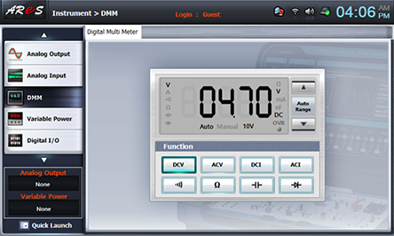
Choose multimeter at the left menu of Touch LCD panel and choose .
Adjust variable resistance R2 and make VR3 as 4.7V, and record the values of base current(IB) on the separate Digital Multimeter in the relevant columns of table 7-1.
- 2AC Amplification Degree Measurement
Compose as in 2. Wiring Diagram> 2) AC Amplification Degree Measurement.
In 3) Measuring Instrument Connection>Ammeter Connection, remove the measuring measurement lead wire of Digital Multimeter between 1f and 1o terminal of Circuit-1 and connect them with yellow. line.
Remove the connection wire for 3) Measuring Instrument Connection>Voltmeter Connection>Measuring the voltage(VR3) of R3’s both ends.
Plug in BNC cable to Signal Output and connect red lead wire to 1a terminal, and black lead wire to 1b terminal.
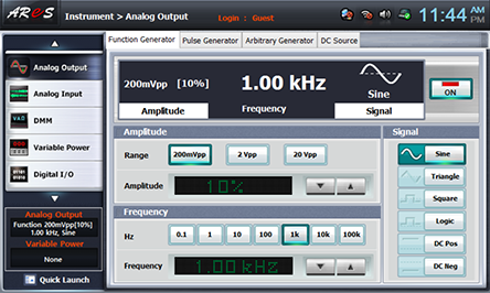
Choose signal output on the left of front panel, click Function Generator and set up Amplitude Range as , Amplitude as amplitude 10 , Frequency as , Signal as and click to output 1kHz 20mVpp.
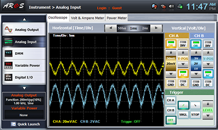
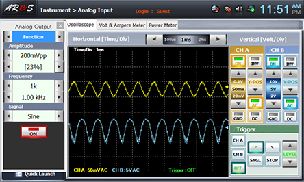
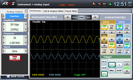
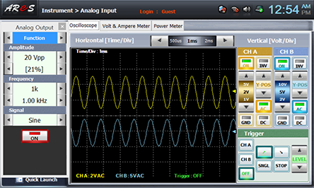
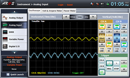
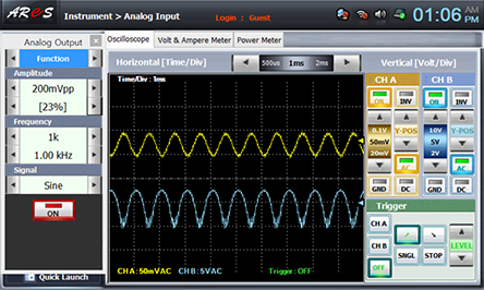
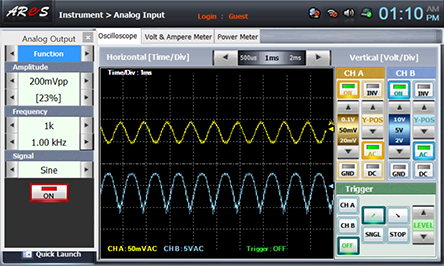
Click signal input on the front panel and set up the Oscilloscope screen to show input/output wave form.
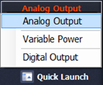
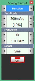
Click quick launch on the left bottom of the screen, choose Analog Output and click at 10% to increase output voltage. Increase it until the signal wave form of CH B is not distorted, draw the wave form of Oscilloscope, calculate input voltage of CH A and distortionless output voltage of CH B and record it in the relevant column of table 7-1.

- 3Measure the amplification degree when IC is 1.25mA, 1.5mA, 1.75mA.
Execute 1)DC Amplification Degree Measurement, 2) AC Amplification Degree Measurement and record the result in the relevant column of table 7-1. The wire connection for 1) DC Amplification Degree Measurement 3) Measuring Instrument Connection>Ammeter Connection and 3) Measuring Instrument Connection>Voltmeter Connection>Measuring the voltage(VR3) of R3’s both ends.
Adjust the value of IC as 1mA following the formula of IC=VR3/R3
In the formula above, VR3=IC R3 so when IC=1mA, R3 = 4.7kΩ, VR3= 4.7V.
When IC=1.25mA, R3 = 4.7kΩ, VR3= 5.87V
When IC=1.5mA, R3 = 4.7kΩ, VR3= 7.05V
When IC=1.75mA, R3 = 4.7kΩ, VR3= 8.225V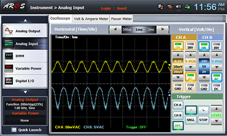


4.Calculation
1. Calculate DC amplification degree(βdc) and AC amplification degree(βdc) and record in the relevant column of table 7-1.
2. Calculate the saturation current and cutoff voltage and record the load line and operating point(Q).
Saturation Current
Cutoff Voltage
Using the graph, calculate the current of operating point(Q) and voltage between collector-emitter.
Fig. 7-3 Circuit (b)
1.Connection(Circuit-1 of M-07)
1.Circuit Connection
Connect between 1g terminal and 1i terminal, between 1f terminal and 1o terminal with yellow lines.
2.Power Connection
It is connected internally
3.Measuring Instrument Connection
Voltmeter Connection for DC Amplification Degree
Measuring the voltage(VR3) of R3’s both ends by using the voltage measurement function of separate Digital Multimeter: Connect the red line of Digital Multimeter to 1d terminal of Circuit-1 and the black line to 1e terminal.
Measuring the voltage(VR4) of R4’s both ends: Connect between 1h terminal of Circuit-1 and High terminal on the front panel of Multimeter with red line, and between 1i(1j,1n) terminal and Low terminal with black line.
Voltmeter Connection for AC Amplification Degree
Measuring input voltage: Connect between 1a terminal of Circuit-1 and A+ terminal of Signal Input CH A on the front panel of Multimeter with red line, and between 1b terminal and A- terminal with black line.
Measuring output voltage: Connect between 1k terminal of Circuit-1 and B+ terminal of Signal Input CH B on the front panel of Multimeter with red line, and between 1l terminal and B- terminal with black line.
2.Wiring Diagram
1) Wiring Diagram for DC Amplification Degree Measurement
flash
2) Wiring Diagram for AC Amplification Degree Measurement
flash
3.Measurement
- 1DC Amplification Degree Measurement
Compose as in 2. Wiring Diagram> 1) DC Amplification Degree Measurement.
Adjust variable resistance R2 and make VR3 as 4.7V, and record the values on the front panel of separate Digital Multimeter in the relevant columns of table 7-2.
Adjust the value of IC as 1mA following the formula of IC=VR3/R3.
In the formula above, VR3=IC R3 so when IC=1mA, R3 = 4.7kΩ, VR3= 4.7V. - 2AC Amplification Degree Measurement
Compose as in 2. Wiring Diagram> 2) AC Amplification Degree Measurement.
Choose analog output on the left of front panel, click Function Generator and set up Amplitude Range as , Amplitude amplitude 10 , Frequency as , Signal as and click to output 1kHz 2Vpp.

Click signal input on the front panel and set up the Oscilloscope screen to show input/output wave form.
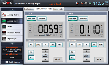
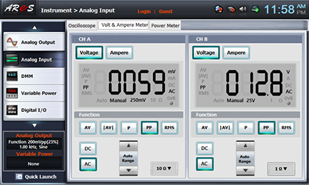
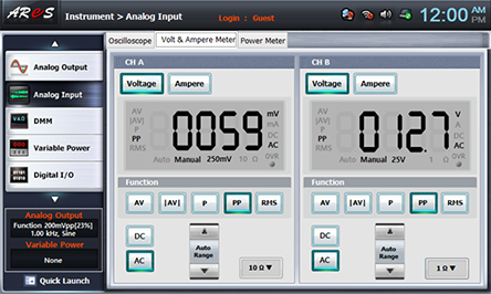
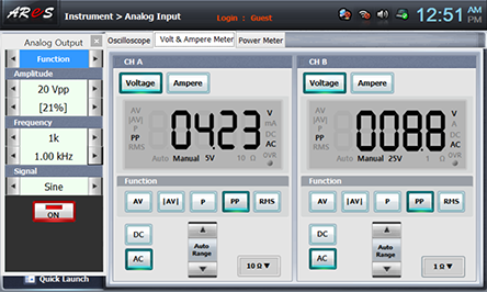
Click quick launch on the left bottom of the screen, choose Analog Output and click at 10% to increase output voltage. Increase it until the signal wave form of CH B is not distorted, draw the wave form of Oscilloscope, click Volt& Ampere Meter tab and record input voltage of CH A and distortion less output voltage of CH B in the relevant column of table 7-2.
- 3Measure the DC and AC amplification degree when IC is 1.1mA, 1.2mA, 1.3mA.
Execute 1)DC Amplification Degree Measurement, 2) AC Amplification Degree Measurement and record the result in the relevant column of table 7-2.
Adjust the value of IC as 1mA following the formula of IC=VR3/R3 In the formula above, VR3=IC R3 so when IC=1mA, R3=4.7kΩ, VR3=4.7V.
When IC=1.1mA, R3 = 4.7kΩ, VR3= 5.17V
When IC=1.2mA, R3 = 4.7kΩ, VR3= 5.64V
When IC=1.3mA, R3 = 4.7kΩ, VR3= 6.11V

4.Calculation
1. Calculate DC amplification degree(βdc) and AC amplification degree(βac) and record in the relevant column of table 7-2.
2. Calculate the saturation current and cutoff voltage and record the load line and operating point(Q).
Saturation Current
Cutoff Voltage
Using the graph, calculate the current of operating point(Q) and voltage between collector-emitter.
Fig. 7-3 Circuit (c)
1.Connection(Circuit-1 of M-07)
1.Circuit Connection
Connect between 1g terminal and 1i terminal, between 1f terminal and 1o terminal, between 1h terminal and 1p terminal, between 1m terminal and 1n terminal with yellow lines.
2.Power Connection
It is connected internally.
3.Measuring Instrument Connection
Connection for DC Amplification Degree
Measuring the voltage(VR3) of R3’s both ends by using the voltage measurement function of separate Digital Multimeter: Connect the red line of Digital Multimeter to 1d terminal of Circuit-1 and the black line to 1e terminal.
Measuring the voltage(VR4) of R4’s both ends: Connect between 1h terminal of Circuit-1 and High terminal on the front panel of Multimeter with red line, and between 1b(1i,1j,1n) terminal and Low terminal with black line.
Voltmeter Connection for AC Amplification Degree
Measuring input voltage: Connect between 1a terminal of Circuit-1 and A+ terminal of Signal Input CH A on the front panel of Multimeter with red line, and between 1b(1i,1j,1n) terminal and A- terminal with black line.
Measuring input voltage: Connect between 1a terminal of Circuit-1 and A+ terminal of Signal Input CH A on the front panel of Multimeter with red line, and between 1b(1i,1j,1n) terminal and A- terminal with black line.
2.Wiring Diagram
1) Wiring Diagram for DC Amplification Degree Measurement
flash
2) Wiring Diagram for AC Amplification Degree Measurement
flash
3.Measurement
- 1DC Amplification Degree Measurement
Compose as in 2. Wiring Diagram> 1) DC Amplification Degree Measurement.
Adjust variable resistance R2 and make VR3 as 4.7V, and record the values on the front panel of separate Digital Multimeter in the relevant columns of table 7-3.
Adjust the value of IC as 1mA following the formula of IC=VR3/R3.
In the formula above, VR3=IC R3 so when IC=1mA, R3 = 4.7kΩ, VR3= 4.7V. - 2AC Amplification Degree Measurement
as in 2. Wiring Diagram> 2) AC Amplification Degree Measurement.
Choose analog output on the left of front panel, click Function Generator and set up Amplitude Range as , Amplitude as amplitude 10, Frequency as , Signal as and click to output 1kHz 20mVpp.

Click signal input on the front panel and set up the Oscilloscope screen to show input/output wave form.
Click quick launch on the left bottom of the screen, choose Analog Output and click at 10% to increase output voltage. Increase it until the signal wave form of CH B is not distorted, draw the wave form of Oscilloscope, click Volt& Ampere Meter tab and record input voltage of CH A and distortion less output voltage of CH B in the relevant column of table 7-2.

- 3Measure the DC and AC amplification degree when IC is 1.1mA, 1.2mA, 1.3mA.
Execute 1)DC Amplification Degree Measurement, 2) AC Amplification Degree Measurement and record the result in the relevant column of table 7-2.
Adjust the value of IC as 1mA following the formula of IC=VR3/R3
In the formula above, VR3=IC R3 so when IC=1mA, R3=4.7kΩ, VR3=4.7V.
When IC=1.1mA, R3 = 4.7kΩ, VR3= 5.17V
When IC=1.2mA, R3 = 4.7kΩ, VR3= 5.64V
When IC=1.3mA, R3 = 4.7kΩ, VR3= 6.11V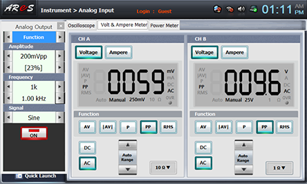
4.Calculation
1. Calculate DC amplification degree(βdc) and AC amplification degree(βac) and record in the relevant column of table 7-3.
2. Calculate the saturation current and cutoff voltage and record the load line and operating point(Q).
Saturation Current
Cutoff Voltage
Using the graph, calculate the current of operating point(Q) and voltage between collector-emitter.
Experiment Result Report
1. Experiment Result Table
1) Calculate DC amplification degree(βdc) and AC amplification degree(βac).
2) Draw input/output wave form.
1) Calculate DC amplification degree(βdc) and AC amplification degree(βac).
2) Calculate value of IB using Ie=Ve/R4, IB=Ie-IC formula.
3) Draw input/output wave form.
1) Calculate value of IB using Ie=Ve/R4, IB=Ie-IC formula
2) Calculate DC amplification degree(βdc) and AC amplification degree(βac).
3) Draw input/output wave form.
2. Review and Explanation
Circuit 7-2(a)
1) Calculate the saturation current and cutoff voltage and record the load line and operating point(Q).
Saturation Current
Cutoff Voltage
Using the graph, calculate the current of operating point(Q) and voltage between collector-emitter.
Circuit 7-2(b)
Calculate DC amplification degree(βdc) and AC amplification degree(βac).
2) Calculate the saturation current and cutoff voltage and record the load line and operating point(Q).
Saturation Current
Cutoff Voltage
Using the graph, calculate the current of operating point(Q) and voltage between collector-emitter.
3. Discuss the experiment result.
1) Compare the characteristics of circuits (a)~(c) in fig. 7-2. Discuss focusing on the factors below.
- (a) circuit : The AC and DC amplification degree is high but it is weak to noise.
- (b) circuit : The AC and DC amplification degree is low but it is strong to noise.
- (c) circuit : The DC amplification degree is low, while AC amplification degree is high, and it is strong to noise.