PART11Oscillation Circuit
Experiment 4 :Hartley Oscillator
Theory
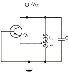
Fig.11-8 is a simple form of Hartley oscillator. Inductor L1 and L2 are one inductor that has a middle tab. Positive feedback can be earned by the mutual inductance between L1 of transistor output circuit and L2 of base-emitter input circuit. In collector circuit(L1), parts of amplifier signal comes back to the base by inductance connection of L1 and L2. In CE circuit, the phase inversion of 180° occurs always between the collector and the base voltage. Also, with the inductor tab connected to the emitter(common terminal of transistor) as the base(L1 - L2 combination), another phase inversion of 180° occurs at the opposite terminals of the inductor. Therefore, if these two are combined, the feedback condition of same phase is realized, and the closed circuit gain is earned by Q1. Here, the oscillation frequency is as below.

And this oscillation frequency is a little bit affected by transistor parameter and the coupling factor between L1 and L2.
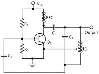
Fig.11-9 shows the actual Hartley oscillator. To produce actually operating oscillator, several circuit elements should be added to the simple circuit in fig.11-8. In the fig., the resistance RA and RB are used for bias, and high frequency circuit(RFC) becomes open circuit in the oscillation frequency so it opens the path for DC bias current but cuts off the signal of AC power. The coupling capacitor C3 cuts off DC current flowing from the tank circuit and C2 hinders the DC coupling between the base and the tank circuit. Compared to C1, C2 and C3 have bigger capacities so they are considered as short circuit in the oscillation frequency.
Experiment Process
1. Using Circuit-4 of M-11, compose a circuit as in fig.11-10. Here, connect C1 only as a capacitor and the capacity should be 100pF.
2. As in table 11-4, record output frequency, output voltage, feedback voltage(voltage between 4c-4h) and calculated frequency in the relevant columns. The feedback rate is (n1/(n1+n2))*100.
3. Next, connect between 4c-4d terminal so the capacity of the capacitor becomes 200pF and repeat process 2.
tab1Experiment 11-4.1 Hartley Oscillator Experiment (In Circuit-4 of M11, compose a circuit as in fig.11-10.)
1.Connection(In Circuit-4of M11, experiment the circuit of fig.11-10.)
1.Power connection is internally connected.
2.Measuring Instrument Connection
Oscilloscope and Voltmeter Connection
Output Voltage Measurement Connection: Connect between 4a terminal of Circuit-4 and A+ terminal of Signal Input CH A on the front panel of Multimeter with red line, and between 4b terminal and A- terminal with black line.
Feedback Voltage Measurement Connection(L1 Voltage): Connect between 4g terminal of Circuit-4 and B+ terminal of Signal Input CH B on the front panel of Multimeter with red line, and between 4h terminal and B- terminal with black line.
2.Wiring Diagram
3.Measurement
- 1Compose a circuit where the capacitor C1(100pF) is connected.
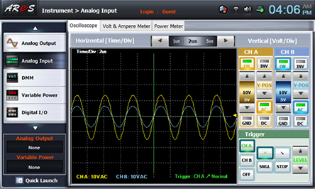
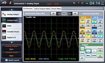
Choose analog input at front panel, draw the output wave form in oscilloscope screen, and record the output frequency and calculated frequency in the relevant columns of table 11-4. Set up the oscilloscope so that the wave form can be optimal.
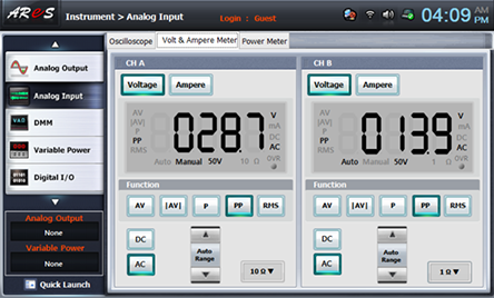
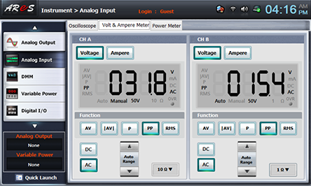
Choose Volt & Ampere Meter tab, click , , at CH A, B, and record the indicated output voltage and feedback voltage(L1 voltage4 in the relevant column of table 11-3.
(CH A : Output Voltage, CH B : Feedback Voltage)
- 2Compose a circuit where the capacitor of 200pF is connected.
To connect the capacitor C2(200pF) to the circuit, connect between 4c-4d terminal of Circuit-4 with yellow line.
Wiring Diagram
Execute 3. Measurement>1) process and record the measured result in the relevant column of table 11-4.
4.Calculation
1. Calculate the frequency using the formula of calculating frequency for Hartley oscillator.

Experiment Result Report
1. Experiment Result Table
2. Review and Explanation
1) Using the wave form in oscilloscope screen, compare the output frequency and calculated oscillation frequency.


