


PART12Pulse Circuit
Experiment 2 :Schmitt Trigger Circuit
Theory
Schmitt trigger circuit is used for voltage level detection, shaping of wave form and so on. As in fig.12-9, two transistors are connected by resistance division and emitter connection When the input, that is, the Tr1 base potential is low, Tr1 is OFF, Tr2 is ON and the emitter current of Tr2 flows to RE so the emitter potential of Tr1 increases and Tr1 is OFF. Also, the collector of Tr1 has high potential so the base current flows to Tr2 through Rk and Tr2 is ON and Tr1 is Off so Tr2 is in the stable state of ON.
Here, the input voltage slowly increases and when it exceeds (VBE = VE) and the base current of Tr1 starts to flow and the collector voltage starts to fall, the base current of Tr2 decreases and the emitter current decreases. Therefore, the emitter voltage of Tr1 starts to fall and the base current of Tr1 increases radically.
According to this positive feedback action, the state is reversed in a moment so Tr1 is ON, Tr2 is OFF. In this state, this time, the emitter potential of Tr1 is determined by Rk and emitter current of Tr1. Next, the input voltage falls and if it goes below this voltage, Tr1 is OFF and the opposite positive feedback is activated so the original state of Tr1-OFF, Tr2-ON is back.
If this state is described in input/output wave form, it is as fig.12-10. Here, the operation level becomes (VBE + REIE) so by making the load resistance of Tr1,Tr2 different and changing the emitter current, the operation level of reversion and that of restoration can be different, and this difference is called hysteresis voltage. Schmitt trigger circuit is used for detecting signals which reached certain setup level, changing certain wave form to square wave, or shaping distorted pulse.
Experiment Process
1. In Circuit-2 of M12, compose a circuit as in fig.12-11 and make the input as sine-wave 1000Hz.
2. As given in table 12-3, measure the output voltage for each input voltage and record the result in the relevant column. Check out the output wave form and compare it with the input wave form.
3. In Circuit-2 of M12, compose a circuit as in fig.12-12 by connecting between 2l-2m, 2d-2f, 2e-2g, 2n-2o terminals.
4. As given in table 12-3, measure the output voltage for each input voltage and record the result in the relevant column. Check out the output wave form and compare it with the input wave form.
tab1Experiment 12-2.1 Schmitt Trigger Circuit Experiment (In Circuit-2 of M12, compose circuits as in fig.12-11, 12.)
Schmitt Trigger Circuit, Fig.12-11 of Circuit-2
1.Connection
1.Power connection is internally connected.
2.Measuring Instrument Connection
Function Generator Connection
Plug in BNC cable to BNC terminal of Signal Output on front panel and connect red line to 2a terminal of Circuit-2, and black line to 2b terminal.
Oscilloscope and Voltmeter Connection
Input Voltage Measurement Connection: Connect between 2a terminal of Circuit-2 and A+ terminal of Signal Input CH A on the front panel of Multimeter with red line, and between 2b terminal and A- terminal with black line.
Output Voltage Measurement Connection: Connect between 2j terminal of Circuit-2 and B+ terminal of Signal Input CH B on the front panel of Multimeter with red line, and between 2k terminal and B- terminal with black line.
2.Wiring Diagram
flash
3.Measurement
- 1In Circuit-2 of M12, compose a circuit as in fig.12-10 and make the input as sine-wave 1000Hz.
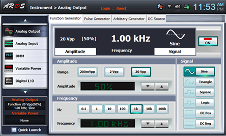
Choose analog output at Touch LCD panel, set up Amplitude Range as , and Amplitude as amplitude 50%. Choose at Frequency to make 1khz. Set up Signal as , and click to send the output to Circuit-2.
In table 12-3, when the input voltage is 10Vpp, 15Vpp, 50% of becomes 10Vpp so measure by setting up the Amplitude as 50%, 75%.
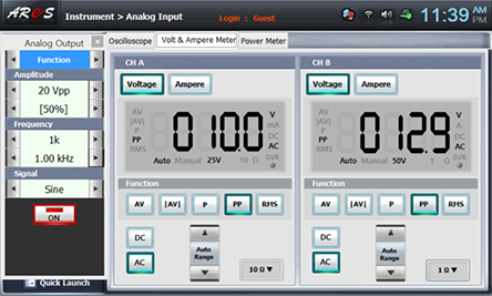
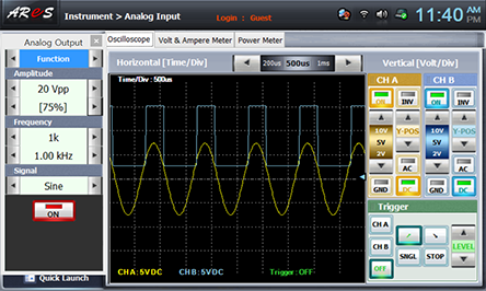
Choose analog_input at front panel and draw the wave form in oscilloscope screen in the relevant column of table 12-3.

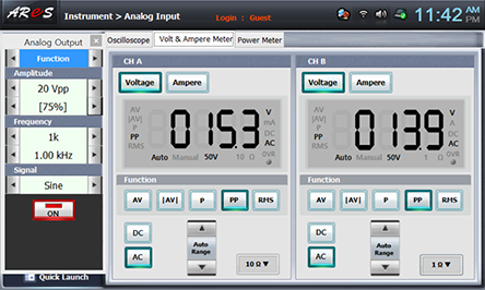
Choose Volt & Ampere Meter tab and click , , at CH A, CH B and record the indicated output voltage in the relevant column of table 12-3.
- 2Measure the output wave form and voltage in case of 15Vpp.
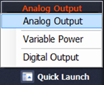
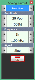
Choose quick launch on the left bottom of the screen, click Analog Output and click of Amplitude 50% to change the amplitude as 75%. Record the indicated output wave form in the relevant column of table 12-3.

- 3In Circuit-2 of M12, compose a circuit as in fig.12-12 by connecting between 2l-2m, 2d-2f, 2e-2g, 2n-2o terminals.
Connect between 2l-2m, 2d-2f, 2e-2g, 2n-2o terminals with yellow lines.
Wiring Diagram
flash
Execute the process 2), 3) above and record the input/output wave form and output voltage in the relevant column of table 12-3.


- 4After the measurement, click at quick launch screen and cut off the output.