


PART1DC Circuit
Experiment Purpose
- 1.Understanding the characteristics of Resistance(R), Current(I) and Voltage(E), and Ohm’s law which explains interrelationship between them.
- 2.Investigating the changes of combined resistance when more than 2 resistances are connected in series or in parallel.
- 3.Using Kirchhoff‘s Law, investigating the branch of current and electric potential of each component in the circuit that has more than two voltage generator.
- 4.Investigating Wheatstone Bridge’s Balance Circuit, which is applied not only to the resistance measurement but also to the sensing circuit of various signals.
Experiment 1 : Ohm’s Law
Theory
Ohm’s law defines the interrelationship between Voltage(E), Current(I), and Resistance(R). That is, it shows that the voltage is in direct proportion to the current and the resistance, and the current is in reverse proportion to the resistance. The voltage is the potential difference between two points and it means the electric (current) pressure. Its symbol is ”E” and unit is “V(Volt)”. The current means the movement of electric charge and the direction to which the electric charge moves is + direction. When indicating the current flowing within the unit time(Sec), the symbol is “I” and the unit is “A(Ampere)”. The resistance, indicated as "R", is the degree of disturbing the flow of current, and the unit is Ω(ohm). When 1A current flows under 1V voltage, the resistance of this circuit is 1Ω. Ohm’ law can be formularized as below.
1-2 shows a basic current circuit. Here, the ammeter is connected to the circuit in serial, and the voltmeter is connected to the load resistance in parallel. Having no resistance means Short, and having infinite resistance means Open. Also, if the resistance is connected to the circuit, Work occurs and this is called Electric Power. Electric power means the amount of work the current does within the unit time, and its symbol is “P” and unit is W(Watt). If the load has regular resistance, P is in proportion to the square of the potential difference(voltage). Electric power can be formularized as below.
Experiment Process
experiment1
Experiment 1-1.1 Ohm’s Law (In Circuit-1 of M-01, compose a circuit as in Fig. 1-3.)
1.Connection (Circuit-1 of M-01)
1.Circuit Connection
Connect between A2 terminal and 1a terminal, between 1b terminal and 1c terminal of Circuit-1 with yellow lines.(R2 Short)
2.Power Connection
Connect com terminal and (-) terminal of 0~10V input to Variable Power with black line, and connect V1 terminal and (+) terminal of 0~10V input to Variable Power with red line.
3.Measuring Instrument Connection
Ammeter Connection
Connect between A1 terminal of Circuit-1 and mA/A terminal of Multimeter Current on the front panel with red line, and between A2 terminal and Low terminal with black line.
Voltmeter Connection
Connect between (+) terminal of 0~10V input and A+ terminal of Signal Input on the front panel with red line, and between (-) terminal and A- terminal with black line.
2.Wiring Diagram
flash
3.Measurement
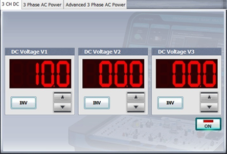
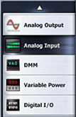
- 1Choose Touch variable power on the left menu of LCD panel.
- 2Choose 3 CH DC tab and click at DC Voltage V1 to set up 10V.
If you double-click DC Voltage V1 and click 1 , 0 and okusing Quick Number Keypad, it can be input directly.
- 3If you click , it is as below and the output of DC 10V is input to the circuit
- 4Choose analog input on the left menu of Touch LCD panel.
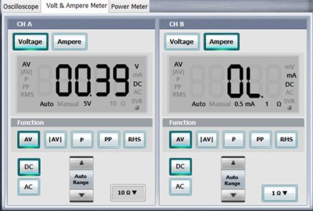
- 5Choose Volt & Ampere Meter tab of main window, click at CH A window,
click andat Function, then record the measured value
of CH A in Fig. 1-3 of table 1-1. CH A means Voltage V-1 of R1’s both ends.
The current shown in CH B is not a measured value but the calculated current for the resistance on the left below.
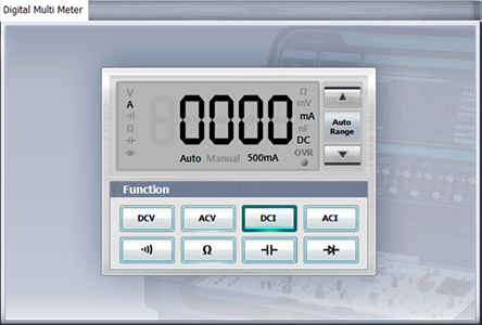
- 6If you click dmmon the left menu, Digital Multi Meter window appears, and if you click ,the current value of A-1 appears. Record it in Fig. 1-3 of table 1-1..
4.Calculation
1. Using the voltage and the current in Fig. 1-3 of table 1-1, calculate the resistance value according to Ohm’s law and record it
Experiment 1-1.2 Ohm’s Law (In Circuit-1 of M-01, compose a circuit as in Fig. 1-4.)
1.Connection (Circuit-1 of M-01)
1.Circuit Connection
Connect between A1 terminal and A2 terminal of Circuit-1 with yellow line.
2.The power connection is same as Experiment 1-1.
3.Measuring Instrument Connection
Ammeter Connection
Connect between A2 terminal of Circuit-1 and mA/A terminal of Multimeter Current on the front panel with red line, and between 1a terminal and Low terminal with black line.
Voltmeter Connection
V-1 voltage measurement: Connect between 1a terminal of Circuit-1 and A+ terminal of Signal Input on the front panel with red line, and between 1b terminal and A- terminal with black line.
V-2 voltage measurement: Connect 1b terminal and B+ terminal of Signal Input with red line, and between 1c terminal and B- terminal with black line.
2.Wiring Diagram
flash
3.Measurement
- 1Choose variable_powerat the left menu of Touch LCD panel.
- 2Choose 3 CH DC tab, click at DC Voltage V1 to set up 10V, click , and the output of DC 10V is input to the circuit.
- 3Choose analog input at the left menu of Touch LCD panel, choose Volt & Ampere Meter tab, choose for CH A and CH B each, and choose and at Function.
Record the measured value of CH A and CH B in Fig. 1-4 of table 1-1. CH A means the voltage V-1 of R1’s both ends and the voltage V-2 of R2’s both ends.
- 4Click dmm at the left menu of Touch LCD panel, click , and the current value is measured. Record it in the Fig. 1-4 of table 1-1..
4.Calculation
1. Using the voltage and current in Fig. 1-4 of table 1-1, calculate the resistance value according to Ohm’s law and record it.
Experiment 1-1.3 Ohm’s Law (In Circuit-1 of M-01, compose a circuit as in Fig. 1-5.)
1.Connection (Circuit-1 of M-01)
1. Circuit Connection
Connect between A1 terminal and A2 terminal, 1b terminal and 1c terminal and 1e terminal and 1f terminal of Circuit-1 with yellow lines.
2. The Power Connection is same as Experiment 1-1.
3. Measuring Instrument Connection
Ammeter Connection
A-1 Current Measurement: Connect between a2 terminal and 1d terminal with yellow line, and between mA/A terminal of Multimeter Current on the front panel and A2 terminal of Circuit-1 with red line, and between Low terminal and 1a terminal with black line.
A-2 Current Measurement: Remove the yellow line between a2 terminal and 1d terminal, and connect between A2 terminal and 1a terminal with yellow line, and between mA/A terminal of Multimeter Current on the front panel and a2 terminal of Circuit-1 with red line, and between Low terminal and 1d terminal with black line
Voltmeter Connection
Connect between (+) terminal of 0~10V input of Curcuit-1 and A+ terminal of Signal Input on the front with red line, and between (-) terminal and A- terminal with black line.
2.Wiring Diagram
A-1 Current Measurement
flash
A-2 Current Measurement
flash
3.Measurement
- 1Choose variable_power at the left menu of Touch LCD panel and click of DC Voltage V1 on 3CH tab to set up 10V.
If you click , the output of DC 10V is input to the circuit. - 2Choose analog_input at the left menu, choose Volt & Ampere Meter tab, of CH A, and click and at Function, and the measured value appears. CH A means the voltage V-1 of R1’s both ends.
- 3Compose the connection as Measuring Instrument>Ammeter Connection>A-1 Current Measurement>and click dmm at the left menu, then Digital Multi Meter window appears. If you click , the current value of A-1 is measured. Record it in Fig. 1-5 of table 1-1.
- 4Compose the connection as Measuring Instrument>Ammeter Connection>A-2 Current Measurement>, then the current value of A-2 is measured. Record it in Fig. 1-5 of table 1-1.
4.Calculation
1. Using the voltage and current in Fig. 1-5 of table 1-1, calculate the resistance value according to Ohm’s law and record it.
Experiment 1-1.4 Ohm’s Law (In Circuit-1 of M-01, compose a circuit as in Fig. 1-6.)
1.Connection (Circuit-1 of M-01)
1.Circuit Connection
Connect between A1 terminal and A2 terminal of Circuit-1 with yellow line.
2.The Power Connection is same as Experiment 1-1.
3.Measuring Instrument Connection
Ammeter Connection
A-1 Current Measurement: Connect between a2 terminal and 1d terminal with yellow line, between mA/A terminal of Multimeter Current on the front panel and A2 terminal of Circuit-1 with red line, and between Low terminal and 1a terminal with black line.
A-2 Current Measurement: Remove the yellow line between a2 terminal and 1d terminal, and connect between A2 terminal and 1a terminal with yellow line,between mA/A terminal of Multimeter Current on the front panel and A2 terminal of Circuit-1 with red line, and between Low terminal and 1a terminal with black line.
Voltmeter Connection
V-1 Voltage: Connect between A+ terminal of Signal Input on the front panel and 1b terminal of Circuit-1 with red line, and between A- terminal and 1c terminal with black line.
V-2 Voltage: Connect between B+ terminal of Signal Input on the front panel and 1e terminal of Circuit-1 with red line, and between B- terminal and 1f terminal with black line.
2.Wiring Diagram
A-1 Current Measurement
Alternative content
A-2 Current Measurement
Alternative content
3.Measurement
- 1 Choose variable_power at the left menu of Touch LCD panel and click of DC Voltage V1 at 3CH tab to set up 10V.
If you click , the output of DC 10V is input to the circuit. - 2 Choose analog_inputat the left menu, choose Volt & Ampere Meter tab, click , , for CH A and CH B each.
Record the measured values of CH A and CH B in Fig. 1-6 of table 1-1. CH A means the voltage V-1 of R2’s both ends and the voltage V-2 of R4’s both ends.
- 3 Compose the connection as Measuring Instrument>Ammeter Connection>A-1 Current Measurement> and click dmm at the left menu, then the current value of A-1 is measured in Digital Multi Meter window. Record it in Fig. 1-6 of table 1-1.
- 4 Compose the connection as Measuring Instrument>Ammeter Connection>A-2 Current Measurement>, then the current value of A-2 is measured. Record it in Fig. 1-6 of table 1-1.
4.Calculation
1. Using the voltage and current in Fig. 1-6 of table 1-1, calculate the resistance value according to Ohm’s law and record it.