PART8Operation Amplifier Circuit(OP AMP)
Experiment 4 :Difference Amplifier
Theory
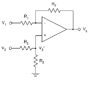
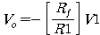
As in fig. 8-10, when input voltage is applied at the same time to the inverting input(-) terminal and non-inverting(+) terminal of OP-Amp, it is composed as difference amplifier. If V2’ point is earthed and V is supposed as “0”, it is similar to fig. 8-2 and becomes a simple inverting amplifier. The output voltage is as below.
![V_o=-[R_f/R1]V1](../image/part8/formal8.14.gif)
If short circuit is removed from V2’ and the input signal V1 is earthed, it is composed as non-inverting amplifier. The actual input voltage of OP-Amp becomes V2’, which is the result of dividing the input voltage V2 at the voltmeter.
![V_o=[1+R_f/R1]V2^'=[1+R_f/R1][R3/(R2+R3)]V2](../image/part8/formal8.15.gif)
Here,
If two formulae above are combined, the output voltage of difference amplifier can be expressed as a function of input voltage V1 and V2.
Here,
![V_o=-[R_f/R1]V1+[1+R_f/R1][R3/(R2+R3)]V2](../image/part8/formal8.17.gif)
While the first term on the right is the inverted output, the second term is non-inverted output. When the circuit in fig. 8-10 is used as a difference amplifier, the voltage gain(G) can be expressed as 4 resistances.
Here,
When all 4 resistances are same, the output voltage becomes as below.
Here,
Therefore, the output voltage becomes the difference between V2 and V1. This circuit is called unit gain(the gain is 1.0) analog subtracter.
tab1Experiment 8-4.1 Difference Amplifier Experiment (Compose as Circuit-5 of M-08.)
DC Difference Amplification Experiment
1.Connection(Circuit-5 of M-08)
1.Power Connection
It is connected internally.
2.Measuring Instrument Connection
Variable Power Connection
Connect between V1 terminal of Variable Power on front panel and 5a terminal of Circuit-5 with red line(Input-1), and between V2 terminal and 5b terminal with red line(Input-2), and between COM terminal and 5c terminal with black line.
Multimeter Connection
Connect between High terminal of Multimeter on front panel and 5f terminal of Circuit-5 with red line, and between Low terminal and 5g terminal with black line.
2.Wiring Diagram
flash
3.Measurement
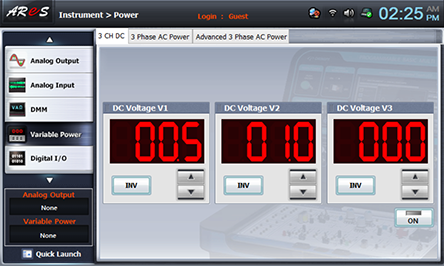
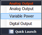
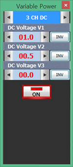
- 1Click variable power at Touch LCD panel and choose 3CH DC.
Click and set up V1 as 0.5V, V2 as 1.0V, and click and output DC to Circuit-5.
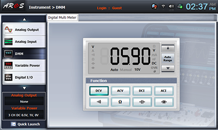
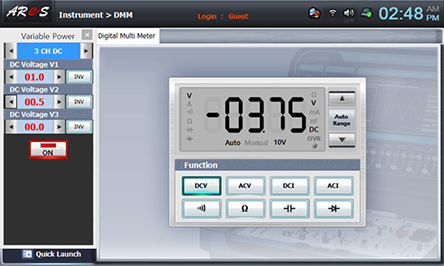
- 2Output Voltage Measurement
Click dmm at Touch LCD panel, choose and record the measured value in the relevant column of table 8-6.
- 3Choose quick launch at the left bottom of Touch LCD panel, click Variable Power and use of DC Voltage V1 and V2 at 3CH DC and adjust as V1(Input-1)=1V, V2(Input-2)=0.5V, and record the measured value of DMM in the relevant column of table 8-6.
After the measurement, click of quick launch screen and cut off the output.
DC Difference Amplification Experiment
1.Connection(Circuit-5 of M-08)
1.Power Connection
It is connected internally.
2.Measuring Instrument Connection
Internal Function Generator Connection
Plug in BNC cable to BNC terminal of Signal Output on front panel and connect red line to 5a terminal of Circuit-5, and black line 5c terminal. (Input-1)
External Function Generator Connection
Plug in BNC cable to output BNC terminal of function generator and connect red line to 5b terminal of Circuit-5, and black line 5c terminal. (Input-2)
Signal Input Connection
Connect between 5f terminal of Circuit-5 and A+ terminal of Signal Input CH A on the front panel of Multimeter with red line, and between 5g terminal and A- terminal with black line.
2.Wiring Diagram
flash
3.Measurement
- 1Function Generator Setting
Choose analog output at Touch LCD panel, click Function Generator and set up Amplitude Range as , Amplitude as amplitude 100% and make the output voltage as 200mVpp.
Set up Signal as , and choose and set up Frequency as frequency 100% and click to apply the output of Function Generator to input of Circuit-5(Input-1).Make the output frequency of separate function generator as 1kHz, the output voltage as 100mVpp and apply it to input of Circuit-5(Input-2).
- 2Measurement
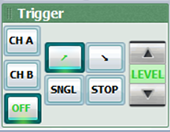
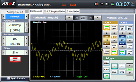
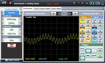
Choose analog input at Touch LCD panel and set up at the Oscilloscope tab as the picture below.

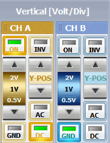
Adjust Y-POS of CH A so that the marker can be located as in the picture below and draw the wave form in the graph of table 8-7.
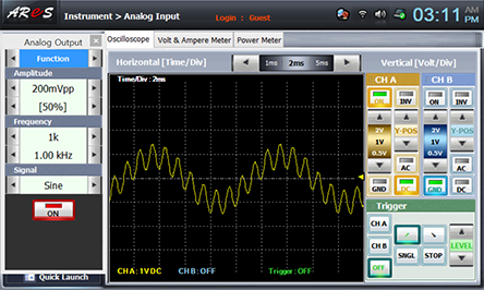
- 3Apply AC input to two input terminals each as given in table 8-7 and following process 1) 2) above and draw the output wave form for each case.
After the measurement, click on quick launch screen and cut off the output.
Experiment Result Report
1. Experiment Result Table
2. Review and Explanation
1) In table 8-6, calculate output voltage using the formula below.
Calculate with the resistances R1, R2, R3, R4 of Circuit-5.