PART13Fundamental Logic Circuit
Experiment 2 :AND Gate / NAND Gate
Theory
In order for the output state of AND gate to become high level, all input state should become high level. Fig.13-6 shows AND gate and truth table.
On the other hand, in NAND gate, if all inputs are high at the same time, the output becomes low. In other cases, the outputs all become high. Fig.13-7 shows NAND gate and truth table.
Experiment Process
1. In Circuit-2 of M13, connect between 2c-2m terminal and compose 2-input AND gate as in fig.13-8(a). LED-1 and LED-2 are turned on when “H” is applied to A and B, and LED-3 indicates the output.
2. Turn on and off switch A and B of 2-input AND gate in table 13-2 and record the output X.
3. Using Circuit-2 of M13, compose a 3-input AND gate circuit as in fig.13-8(b).
4. To turn on A, B and C, connect between 2e-2f terminal for input A, between 2g-2h terminal for input B, and between 2i-2j terminal for input C. Record the output for each input of 3-input AND gate in table 13-2.
5. In Circuit-2 of M13, connect an inverter to 2c-2m terminal and compose a NAND gate circuit as in fig.13-9. That is, turn off S2 in Circuit-4 of M13 and connect between 2c-4c, 2m-4e.
6. Measure the output between 2c-2m’s both ends for each input and record the result in the output column of AND gate and record in the output column of table 13-3 NAND gate according to the lighting of LED-3.
tab1Experiment 13-2.1 AND Gate Circuit Experiment (In Circuit-2 of M13, compose circuits as in fig. 13-8(a), (b).)
2 Input AND Circuit
1.Connection
1.Circuit Connection
Circuit-2 of M13, connect between 2c terminal and 2m terminal with yellow line.
2.Power connection is internally connected.
3.Measuring Instrument Connection
Input Voltage Measurement
Connect between 2a terminal of Circuit-2 and A+ terminal of Signal Input CH A on the front panel of Multimeter with red line, and between 2d terminal and A- terminal with black line.
Connect between 2b terminal and B+ terminal of CH B with red line, and between 2d terminal and B- terminal with black line.
Output Voltage Measurement
Connect between 2m terminal of Circuit-2 and High terminal on the front panel of Multimeter with red line, and between 2d terminal and Low terminal with black line.
2.Wiring Diagram
flash
3.Measurement
- 1In Circuit-2 of M13, compose a 2-input AND circuit as in fig.13-8(a).
Measure the voltage applied to AND gate input(LED1, LED2) using switch A(S1) and switch B(S2) and operating “ON”, “OFF” as in table 13-2, record the output as “ON” when LED 3 is on, and as “OFF” when off. Measure and record the voltage of each case. (CH A = S1, CH 2 = S2), (LED1, LED2 are turned on when “H” is applied to A and B, and LED3 indicates the output.)
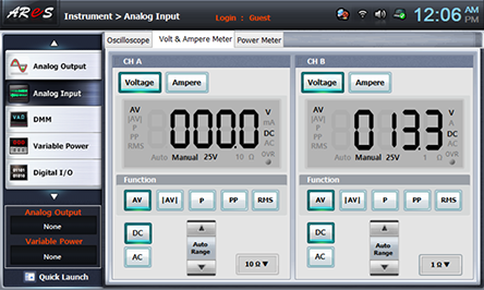
When the SW is located at “L”, it is connected to GND, which is 0 potential. And when it is located at “H”, +15V potential is connected to the circuit.) - 2Input Voltage Measurement: Choose analog input at Touch LCD panel, choose Volt & Ampere Meter tab, click , , at CH A and CH B and record the measured output voltage in the relevant column of table 13-2. (CH A = A Input(S1), CH 2 = B Input(S2))

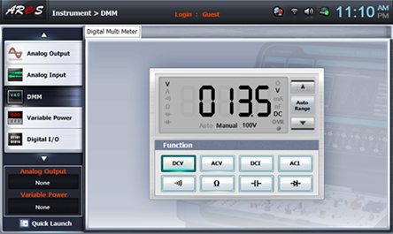
- 3Output Voltage Measurement: Choose dmm at Touch LCD panel, click and record the measured output voltage in the relevant column of table 13-2.
3 Input AND Circuit
1.Connection
1.Power connection is internally connected.
2.Measuring Instrument Connection
AND2,AND3 Output Voltage Measurement
Connect between 2k terminal of Circuit-2 and A+ terminal of Signal Input CH A on the front panel of Multimeter with red line, and between 2d terminal and A- terminal with black line.
Connect between 2l terminal and B+ terminal of CH B with red line, and between 2d terminal and B- terminal with black line.
2.Wiring Diagram
flash
3.Measurement
- 1In Circuit-2 of M13, compose a 3-input AND gate circuit as in fig.13-8(b).
To turn on A, B and C, connect between 2e-2f terminal for input A, between 2g-2h terminal for input B, and between 2i-2j terminal for input C. Record the output for each input of 3-input AND gate in table 13-2.
Measure and record the output voltages of AND2 and AND3 in table13-2.
- 2Output Voltage Measurement: Choose analog input at Touch LCD panel, choose Volt & Ampere Meter tab, click , , at CH A and CH B and record the measured output voltage in the relevant column of table 13-2. (CH A = AND2 Output Voltage, CH 2 = AND3 Output Voltage)
2 Input NAND Circuit
1.Connection
1.Circuit Connection
In M13, connect between 2c terminal of Circuit-2 and 4c terminal of Circuit-4, and between 2m terminal and 4e terminal with yellow lines. Here, turn off S2 of Circuit-4.
2.Power connection is internally connected.
3.Measuring Instrument Connection
AND1 Gate, NOT Gate Output Voltage Measurement
Connect between 2c terminal of Circuit-2 and A+ terminal of Signal Input CH A on the front panel of Multimeter with red line, and between 2d terminal and A- terminal with black line.
Connect between 2m terminal and B+ terminal of CH B with red line, and between 2d terminal and B- terminal with black line.
2.Wiring Diagram
flash
3.Measurement
- 1Circuit-2 and Circuit-4 of M13, compose a NAND gate circuit as in fig.13-9.
- 2Output Voltage Measurement: Choose analog input at Touch LCD panel, choose Volt & Ampere Meter tab, click , , at CH A and CH B and record the measured output voltage in the relevant column of table 13-2. (CH A = AND2 Output Voltage, CH 2 = AND3 Output Voltage)
Measure the output voltage of AND1 gate and NOT gate using switch S1 and switch S2 and operating “ON”, “OFF” as in table 13-3, record the output as “ON” when output LED1(red) is on, and as “OFF” when off.
- 3Output Voltage Measurement: Choose analog input at Touch LCD panel, choose Volt & Ampere Meter tab, click , , at CH A and CH B and record the measured output voltage in the relevant column of table 13-3. (CH A = AND1 Gate Output, CH 2 = NOT Gate Output)