PART7Amplifier Circuit(Transistor AMP)
Experiment 2 :Common Emitter Amp
Theory
Input Impedance

The input impedance of amplifier Zin or Rin is determined by the ratio of distortionless input signal voltage Vin and input signal current iin.
Therefore, Rin can be earned by measuring and inputting Vin and ii in the formula above. The input(base) current of amplifier can be measured by AC micro ammeter or mili ammeter, and fig. 7-4 can be modified to determine with voltmeter-ammeter method. Potentiometer RX is connected between point A and B as in fig. 7-4. RX changes until the voltage VX of RX’s both ends becomes same as the signal voltage Vin measured between B and C. The measured value of detaching RX from the circuit is same as Rin. The input impedance of emitter common amplifier can be increased by executing degeneracy feedback to the input circuit. With same Vin value, the input signal current of base to emitter decreases because of R3. However, just as in the circuit, if there is C3, bypass is possible in AC way. Therefore, when there is degeneracy in the emitter circuit, the value of Rin increases more.
That is,
Output Impedance
The output impedance Zout of the amplifier can be earned experimentally by adding the variable resistor Rout to the output of circuit, and the process is as below. First, measure the output signal Vout without adding the load. Then connect the load and adjust it(Rout) till the new output signal Vout becomes half of the previously measured value Vout and remove Rout from the circuit and measure the value. The measured resistance value is the output impedance Zout. When measuring input/output impedance, make sure there is no distortion on the input/output signal.
Voltage Gain
Emitter earthing amplifier is the amplifier for voltage, current and power. Experimentally, the voltage gain of the amplifier can be determined by inserting measured signal voltage to the input. The output-signal voltage is measured(oscilloscope or AC voltmeter) and the ratio of input signal to output signal becomes the voltage gain.
One important thing is that the amplifer should be operated within the linear region during this process. The linear operation range for this amplifier can be determined experimentally. Input 100Hz sine wave of audio signal to the input and check out the output at oscilloscope collector. Make the output of signal generator at the minimum at first. When the output of the generator increases more and more, observe the wave form with the oscilloscope. And if the measured value is input on the oscilloscope screen till there is no distortion, this is the range of signal input.
Experiment Process
tab1
Experiment 7-2.1 Common Emitter Amp Measurement (In Circuit-3 of M-07, compose a circuit as in fig. 7-5.)
Non Bypass Circuit for Input Impedance Measurement
1.Connection(Circuit-3 of M-07)
1.Circuit Connection
To connect R6 to the circuit, connect between 3d terminal and 3l terminal, between 3n terminal and 3m terminal of Circuit-3 with yellow lines.
2.Power Connection
It is connected internally.
3.Measuring Instrument Connection
Plug in BNC cable to Signal Output of front panel and connect red line to 3a terminal of AC input of Circuit-3, and black line 3b terminal.
Measuring input voltage: Connect between 3a terminal of Circuit-3 and A+ terminal of Signal Input CH A on the front panel of Multimeter with red line, and between 3b terminal and A- terminal with black line.
Measuring output voltage: Connect between 3g terminal of Circuit-3 and B+ terminal of Signal Input CH B on the front panel of Multimeter with red line, and between 3h terminal and B- terminal with black line.
2.Wiring Diagram
flash
3.Measurement
- 1Adjust R1 as maximum, and R6 as minimum (0Ω)
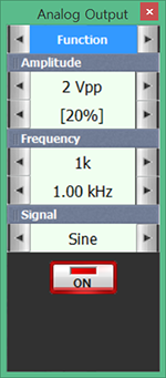
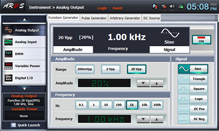
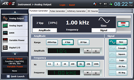
- 2Choose analog output on the left of front panel, click Function Generator and set up Amplitude Range as , Amplitude as amplitude 20, Frequency as , Signal as and click to output 1kHz 40mVpp

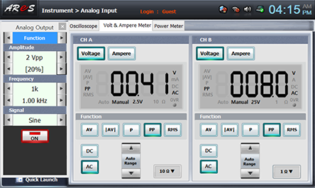
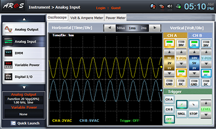
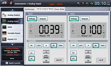
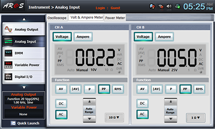
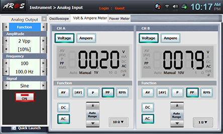
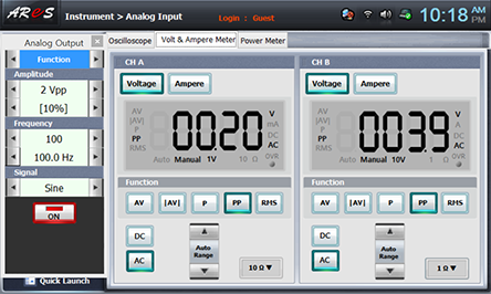
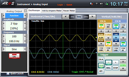
Click signal input at the front panel and choose Volt & Ampere Meter to check out the output voltage of CH A. Here, choose of CH A, CH B at Volt & Ampere Meter screen and choose , at Function.

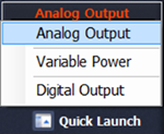
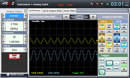
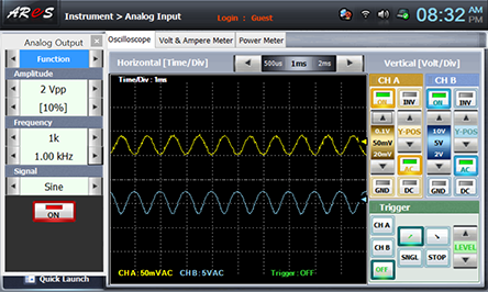
Click quick launch on the left bottom of the screen, choose Analog Output and click at 10% to increase output voltage. Increase it until the signal wave form of CH B becomes 8Vpp. Choose oscilloscope tab to check out whether the output wave form is distorted or not.

Record the measured value of CH A in the relevant column of table 7-4.
- 3Change R6 so that the output voltage becomes 4VPP.

- 4Measure the input voltage VR6, VR3 and record the result in table 7-4.
To measure VR6 voltage, change 3a terminal of Circuit-3 connected for input voltage measurement to 3l terminal and change 3b terminal to 3m terminal and connect.
To measure VR3 voltage, change 3g terminal of Circuit-3 connected for output voltage measurement to 3n terminal and change 3h terminal to 3k terminal and connect.

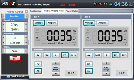
Record the measured value of CH A, CH B in the relevant column of table 7-4.
Click to cut off the signal output.
- 5Remove R6 from the circuit and measure the resistance value. Be careful not to change the resistance value when detaching R6 from the circuit.
Remove the line connected between 3l terminal and 3m terminal and connect between Multimeter High of front panel and 3l terminal with red line, and between Low terminal and 3m terminal with black line.
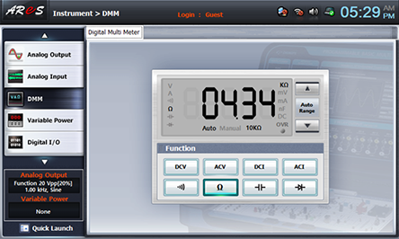
Click multimeter at the left of Touch LCD panel, choose at Function and record the measured value in the relevant column of table 7-4.

- 6With separated digital multimeter, measure DC voltage of each terminal of the transistor for the measuring position given in table 7-4 and record the result.
Bypass Circuit for Input Impedance Measurement
1.Connection(Circuit-3 of M-07)
1.Circuit Connection
To connect R6 to the circuit, connect between 3d terminal and 3l terminal, between 3n terminal and 3m terminal of Circuit-3 with yellow lines.
To connect C3 to the circuit, connect between 3i terminal and 3j terminal with yellow line.
2.Power Connection: It is connected internally.
3.Measuring Instrument Connection: It is same as the measuring instrument connection for [Non Bypass Circuit for Input Impedance Measurement].
2.Wiring Diagram
flash
3.Measurement
- 1Adjust R1 as maximum, and R6 as minimum (0Ω)
- 2Choose analog output on the left of front panel, click Function Generator and set up Amplitude Range as , Amplitude as amplitude 20, Frequency as , Signal as and click to output 1kHz 40mVpp

Adjust R1 so that the output voltage of CH B becomes 8Vpp.

Record the measured value of CH A in the relevant column of table 7-4.
- 3It is same as [Non Bypass Circuit for Input Impedance Measurement]>3. Measurement>3).

- 4It is same as [Non Bypass Circuit for Input Impedance Measurement]>3. Measurement>4).
- 5It is same as [Non Bypass Circuit for Input Impedance Measurement]>3. Measurement>5).

Non Bypass Circuit for Output Impedance Measurement
1.Connection(Circuit-3 of M-07)
1.Circuit Connection
Connect between 3d terminal and 3n of Circuit-3 with yellow line.
2.Power Connection
It is connected internally.
3.Measuring Instrument Connection
Plug in BNC cable to Signal Output of front panel and connect red line to 3a terminal of AC input of Circuit-3, and black line 3b terminal.
Measuring input voltage: Connect between 3a terminal of Circuit-3 and A+ terminal of Signal Input CH A on the front panel of Multimeter with red line, and between 3b terminal and A- terminal with black line.
Measuring output voltage: Connect between 3g terminal of Circuit-3 and B+ terminal of Signal Input CH B on the front panel of Multimeter with red line, and between 3h terminal and B- terminal with black line.
2.Wiring Diagram
flash
3.Measurement
- 1Change R1 and the voltage of input signal and make the output voltage as distortionless maximum value and measure V0 of no load.
Choose analog output on the left of front panel, click Function Generator and set up Amplitude Range as , Amplitude as amplitude 20, Frequency as , Signal as and click to output 1kHz 4Vpp
Adjust R1 so that the output wave form becomes maximum without distortion.
Record the measured value of CH B(V0 with no load) in the relevant column of table 7-5.
- 2Connect R6 to the circuit and change so that it becomes exactly 1/2 of V0 with no load and measure Vi(VR3) and V0 with 1/2 load.
Connect between 3l terminal and 3g terminal, between 3m terminal and 3h terminal of Circuit-3 with yellow lines.
To measure Vi(VR3), change 3a terminal of Circuit-3 connected for input voltage measurement to 3n terminal, and 3b terminal to 3k terminal and connect.
Adjust R6 so that the measured value of CH B becomes 1/2 of V0 with no load.
Record the measured value of CH A, CH B in the relevant column of table 7-5.
Click to cut off the signal output.
- 3Detach R6 from the circuit and measure the resistance. Make sure the resistance value does not change when detaching R6 from the circuit.
Remove the line connected between 3l terminal and 3m terminal and connect between Multimeter High terminal of front panel and 3l terminal with red line, and between Low terminal and 3m terminal with black line.
Click multimeter at the left of Touch LCD panel, choose at Function and record the measured value in the relevant column of table 7-5.
Bypass Circuit for Output Impedance Measurement
1.Connection(Circuit-3 of M-07)
1.Circuit Connection
Connect between 3d terminal and 3n terminal, between 3i terminal and 3j terminal of Circuit-3 with yellow lines.
To connect C3 to the circuit, connect between 3i terminal and 3j terminal with yellow line.
2.Power Connection: It is connected internally.
3.Measuring Instrument Connection: It is same as the measuring instrument connection for [Non Bypass Circuit for Output Impedance Measurement]>1. Connection>3).
2.Wiring Diagram
flash
3.Measurement
- 1Change R1 and the voltage of input signal and make the output voltage as distortionless maximum value and measure V0 of no load.
Choose analog output on the left of front panel, click Function Generator and set up Amplitude Range as , Amplitude as amplitude 10, Frequency as , Signal as and click to output 1kHz 20mVpp.
Adjust R1 so that the output wave form becomes maximum without distortion.


Record the measured value of CH B(V0 with no load) in the relevant column of table 7-5.
- 2Execute [Non Bypass Circuit for Output Impedance Measurement]>3. Measurement>2) and 3) and record the result in table 7-5.

- 3Measuring Characteristic of Amplifier Frequency
In fig. 7-5, connect C2 and measure distortionless maximum output/input of input signal with no load and with rated load as in table 7-6.The output resistance value of Bypass in table 7-5 is used as the rated load.
Choose analog output on the left of front panel, click Function Generator and set up Amplitude Range as , Amplitude as amplitude 10, Frequency as , Signal as and click to output 1kHz 20mVpp.
4.Calculation
1. Calculate the amplification degree (V0/Vi) for each case and record it in table 7-6.
Experiment Result Report
1. Experiment Result Table
1) In table 7-4, how much is the input impedance?
2) Calculate each terminal voltage of transistor and compare it to the measured value.
3) In table 7-5, how much is the input impedance?
4) In table 7-6, calculate the amplification degree (V0/Vi) for each case.
2. Review and Explanation
1) Using table 7-6, draw a frequency characteristic curve in the graph below.
Red line: no load, blue line: load