


PART8Operation Amplifier Circuit(OP AMP)
Experiment 3 :Non-inverting Amplifier
Theory
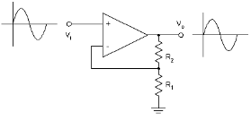
As in fig. 8-9, OP-Amp can be composed as non-inverting amplifier. This is because the input signal is applied to non-inverting (+) input terminal.
Resistance R1 is called input factor, and R2 feedback factor, and the name feedback factor is put because parts of output voltage are feedback to one of OP-Amp’s inputs. In this case, parts of output are back as inverted (-) input. The output voltage of non-inverting amplifier is given as below.
![V_O=[1+R2/R1] V_i](../image/part8/formal8.9.gif)
The ratio of output voltage to voltage gain or input voltage is as below.
As a result, no matter how big the value or R1 becomes, the voltage gain of non-inverting amplifier always becomes bigger than 1.0. Because the input signal is applied to the non-inverting input terminal of OP-Amp, the output voltage becomes always same phase to the input voltage. To put it simply, when the input voltage becomes constant, the output voltage also becomes constant. The difference between input voltage and output voltage is that the output voltage becomes 1+R2/R1 times bigger than the input voltage. Open loop gain AOL is the characteristic when the feedback is not applied to OP-Amp. If there is feedback, it becomes as close loop gain ACL and the voltage gain for this circuit is as below.
Loop gain AL is the division of open loop gain by close loop gain and it can be expressed as below.
In practical purpose, the impedance of non-inverting amplifier is the inherent input impedance of OP-Amp and this is high enough to make the load of input circuit as minimum. Meanwhile, the output impedance of the circuit in ifg.8-9 is determined by the formula below.
![Z_o=Z_oi/A_L =Z_oi [(1+R2/R1)/A_OL ]](../image/part8/formal8.13.gif)
Here, Zoi is the inherent output impedance of OP-Amp determined by the specifications of manufacturer.
tab1Experiment 8-3.1 Non-inverting Amplifier Experiment (Compose as Circuit-4 of M-08)
1.Connection(Circuit-4 of M-08)
1.Power Connection
It is connected internally.
2.Measuring Instrument Connection
DC Source, Function Generator Connection
Plug in BNC cable to BNC terminal of Signal Output on front panel and connect red line to 4a terminal of Circuit-4, and black line to 4b terminal.
Signal Input Connection
Connect between 4a terminal of Circuit-4 and A+ terminal of Signal Input CH A on the front panel of Multimeter with red line, and between 4b terminal and A- terminal with black line.
Connect between 4d terminal of Circuit-4 and B+ terminal of Signal Input CH B on the front panel of Multimeter with red line, and between 4g terminal and B- terminal with black line.
2.Wiring Diagram
flash
3.Measurement
- [DC Amplification Degree Measurement]
1Choose analog output at Touch LCD panel, click DC Source and set up DC Voltage as 1V.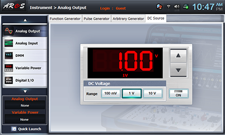
Click and apply the output of DC Source to the input of Circuit-4.
- 2Measurement
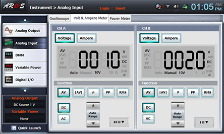
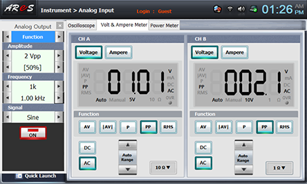
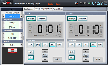
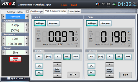
Connect between 4c terminal of feedback resistance R1(10kΩ) in Circuit-4 and 4e terminal with yellow line, choose analog input at front panel, choose Volt & Ampere Meter tab and click , , at CH A, CH B and record the measured value in the relevant column of table 8-5.
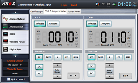
Change the connection between 4c terminal and 4e terminal of feedback resistance R1(10kΩ) in Circuit-4 to connection between 4c terminal and 4f terminal of feedback resistance R2(100kΩ) and record the measured value in the relevant column of table 8-5.
- 3After the measurement, choose analog output and click of DC Source to cut off the output.
- [AC Amplification Degree Measurement]
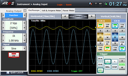
4 Choose analog output at Touch LCD panel, click Function Generator and set up Amplitude Range as , Amplitude as amplitude 50% and make the output as 1Vpp. .
Set up Signal as , and choose and set up Frequency as frequency 1 khzand click to apply the output of Function Generator to input of Circuit-4.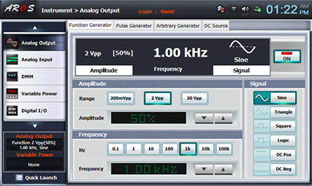
- 5Measurement
Connect between 4c terminal and 4e terminal of Circuit-4 with yellow line, choose analog input at Touch LCD panel, choose Volt & Ampere Meter tab and click , , at CH A, CH B and record the measured value in the relevant column of table 8-5.

Change the connection between 4c terminal and 4e terminal of Circuit-4 to connection between 4c terminal and 4f terminal and record the measured value in the relevant column of table 8-5.
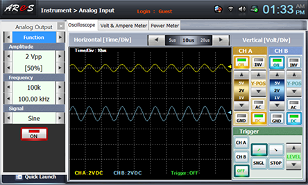
Change the frequency as 100KHz and execute process 5) and record the result in the relevant column of table 8-5.
After the measurement, choose analog output and click of Function Generator to cut off the output.
4.Calculation
1. With the value of R2 in table 8-5 and the resistance value of R1 in Circuit-1, calculate the output voltage with the formula below and record it.
![V_O=[1+R2/R1] V_i](../image/part8/c3.gif)
2. With the measured value in table 8-5, calculate close loop gain(ACL) with the formula below and record it.
Experiment Result Report
1. Experiment Result Table
2. Review and Explanation
1) In the non-inverting amplifier, the formula to calculate output voltage is as below.
In Circuit-4, with the resistances R1, R2, R3 and the formula above, calculate the calculated value and amplification degree of table 8-5.
2) In non-inverting amplifier, the close loop gain(ACL) is as below.
In Circuit-4, with the resistances R1, R2, R3 and the formula above, calculate the close loop gain(ACL) of table 8-5.